46
6.3.3 “Lift distance” and “plunge distance” parameters:
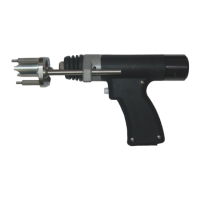
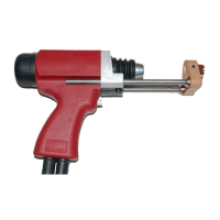
• The mechanical parameters must be set on the respectively connected weld
gun NS 40-B or NS 40 SL.
• See the operating instructions of the corresponding weld gun for
the settings.
• See the gun operating instructions and diagrams below respectively for the
guide values for the welding method.
Lift Settings
Maximum lift height (at +/-10% of rated input voltage, NS40 and NS 40
SL): 2.5mm
(0.1”).
Proper gun lift settings are as follows:
1. All studs within the weld range are listed at 2mm lift and below.
2. The plunge also needs to be appropiately set.
3. When the E009 error appears the lift and plunge should be
reviewed.
4. If the error is E004 or E007 it generally means no pilot arc.
5. Check input voltage from unit control panel using F18 and read
capacitor
voltage.
6. If the lift capability is marginal, i.e. it lifts a low lift height, but fails
to lift at
slightly higher lift height, consult your Nelson Rep.
6.3.4 Calibrate the gun drop time F31
It is recommended to calibrate the gun so that the welder understands the gun drop
time and delivers the precise main arc time programmed. The calibration is a good
practice when you exchange the gun, especially when you change process
between short cycle mode (maximum main arc time is 100 ms) and drawn arc
(minimum main arc time is 100 ms), or change gun type or plunge dampener (shock
absorber). Simply go to F31, and shoot a stud. The actual gun speed is measured