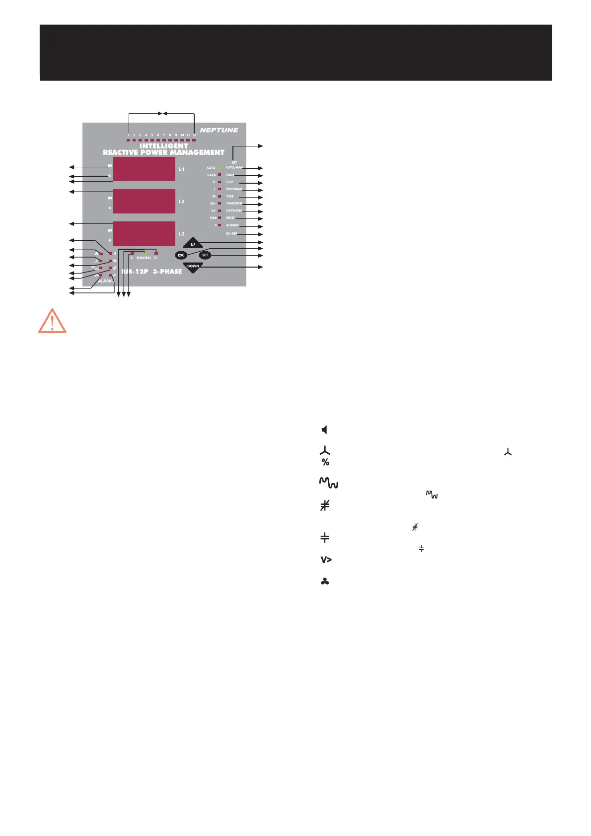
1.2.b Front Panel Functions
INTELLIGENT REACTIVE POWER MANAGEMENT
RM-12P
In order to enter to the menu, SET button
must be pressed for 3 seconds.
3
Display of phase 1.
Display of phase 2.
Display of phase 3.
Go to next menu or increase related value.
Exit from a menu or cancel the data entry.
(In the measurement mode, it is used to exit from
harmonic menu)
Enter to a menu or confirm the data entry.
(In the measurement mode, it is used to observe
the harmonic values of current, voltage and
power values)
Go to the previous menu or decrease related
value.
Represents measurement values with mega unit
(x10
6
).
Represents measurement values with kilo unit
(x10
3
).
Shows the status of each capacitor steps.
Programmable menus which are set by pressing
SET button for 3 seconds.
Indicates if the operating mode is automatic or
manual.
(If it is continuously ON, RM-12P operates in
Automatic Mode. If it blinks, RM-12P operates
in Manual Mode)
If Cosj light is ON, target Cosj value can be set
between Inductive 0,8 - Capacitive 0,8
(In the measurement mode, Cosj values of
related phases are displayed).
Press SET button for 3 seconds, select STEP/V
light to select step number
(In the measurement mode, voltage values of
related phases are displayed).
Press SET button for 3 seconds, select
PROGRAM/I light to select power sequence
program.
(In the measurement mode, current values of
related phases are displayed)
Press SET button for 3 seconds, select TIME/W
led to set switching on delay time, switching off
delay time and discharge time.
(In the measurement mode, active power and
total active power (Ind./Cap.) values of related
phases are displayed)
1. L1
2. L2
3. L3
4. Up Button
5. Esc Button
6. Set Button
7. Down Button
8. M Led
9. k Led
10. 1,2,3,.......,12 Leds
11. SET Menu
12. OTO/MAN Led
13. Cosj Led
14. Step / V Led
1 5. Program / I Led
16. Time / W Led
:
:
:
:
:
:
:
:
:
:
:
:
:
:
:
:
17. Capacitors / VAr Led
18. Network / VA Led
19. Reset / HAR Led
20. Alarm / h Led
21. RS-485
22. C- Led
23. Normal Led
24. C+ Led
25.
26.
27.
28.
29.
30.
31.
32.
:
:
:
:
:
:
:
:
:
:
:
:
:
:
:
:
Press SET button for 3 seconds, select
CAPACITORS/VAr led to set capacitor values
and capacitor connections (R, S, T, RST).
(In the measurement mode, reactive power
and total reactive power values of related
phases are displayed).
Press SET button for 3 seconds, select
NETWORK/VA led to set current transformer
ratio (Ctr), Voltage transformer ratio (Vtr) and
calculation method (Calc).
(In the measurement mode, apparent power
and total apparent power values of related
phases are displayed)
Press SET button for 3 seconds, select
RESET/HAR led to reset energy values,
reactive energy ratios and alarms.
Press SET button for 3 seconds, select
ALARM/h led to set alarms for overvoltage,
reactive/active ratio, temperature and
harmonics.
In this menu, address, baudrate and parity
values for RS-485 communication protocol are
set.
This led represents that RM-12P is waiting for
switching capacitor steps off.
This led represents that RM-12P will not switch
any capacitor steps on&off.
This led represents that RM-12P is waiting for
switching capacitor steps on.
In case of any failure, alarm relay switches on
and alarm led lights.
In case of connection failure,
led lights.
If reactive energy ratios exceed preset values,
% led lights.
If voltage harmonic ratios exceed preset
values,
led lights.
When target power factor value is not reached
although all the capacitor steps are switched
on,
led lights.
If capacitor is not connected to the related
step,
lights is ON.
When voltage value exceeds preset value,
V> light is ON.
When measured temperature value increase
fan measured value after 10 second fan led
light will be on (This is optional).
225.5
228.7
223.4
2423 22
12
13
14
15
16
17
18
19
21
11
4
20
7
6
5
26
27
29
30
31
25
9
1
3
2
28
8
32
10