INTELLIGENT REACTIVE POWER MANAGEMENT
RM-12P
8
3.4 Switching Program Setting
RM-12P has 10 different program modes which determines the
power ratio sequence of the capacitor steps.
Three different switching programs are supported by RM-12P.
a) Linear Operation: The switching program begins always from
the first step to the last one in both switching on and off mode.
The advantage of this switching program is the possibility of a
large selection of capacitor steps. This switching program is
selected by 01 option.
b) Rotational Switching: This switching program is rotational
between equal steps in the clockwise direction and this switching
program is rotational to ensure that the capacitor switching cycles
are uniformly distributed over all steps and to provide minimum
switching steps for maximum service life time of the system.
There are 8 different rotational switching programs (02, 03, 04,
05, 06, 07, 08, 09).
The ratio between capacitor steps is very important. When choosing
the ratio between capacitor steps, the rating of each capacitor
step value may exceed that of the first by a maximum amount
equal to the of the preceding capacitor steps value.
c) PS-10 Program: If PS10 program is selected, RM-12P
calculates electrical parameters of the capacitor steps
automatically. RM-12P counts swithing on&off times of all capacitor
steps and so most necessary step is switched on.
Thus, maximum service life time of the system is ensured.
NOT: In PS-10 program, connection types and power values of the
single phase capacitor steps can be set by user. In Auto setup mode
power values of all capacitor steps are measured.
In other switching programs, only first capacitor steps power value
can be set (except PS-10 program). Other capacitor steps power value
are calculated automatically according to the first capacitor steps
power value.
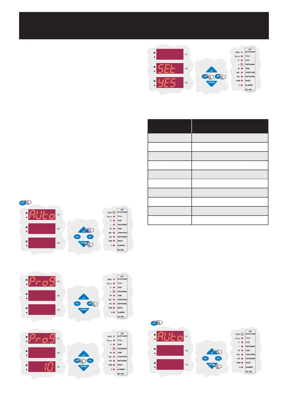
Press UP/DOWN buttons to select program (Prog) menu.
In this menu capacitor steps sequence is selected.
When program menu is displayed, program led lights.
SAUE
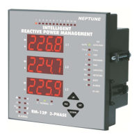
If you do not want to set another parameter, in order to quit from the
menu, press ESC button one by one until SAVE SEt yES is displayed.
Press SET button to save your changes or press ESC button to quit
without saving.
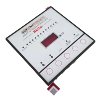
Press SET button to select the switching program.
Enter desired program number between 01-10 and press SET
button. If you do not want to set another parameter press ESC
button.
PROGRAM SEQUENCE
01
02
03
04
05
06
07
08
09
*10
linear
1.1.1.1................
1.1.2.2................
1.2.2.2................
1.2.3.3................
1.2.4.4.................
1.1.2.4................
1.2.3.4................
1.2.4.8................
Capacitor step values are calculated automatically.
* Recommended switching program.
In order to decrease harmful effects of instant reactive power loads to the
relays and capacitors, delay time (in terms of seconds) for capacitor steps
is entered in this menu.
Switch-on delay time must be set according to system requirement in
order to achieve compensation targets and also to provide long life time
for contactors and capacitors.
3.5.a Switch-On Delay Time Setting
Note: t-on and t-of time periods must be set according to the systems
requirements. If t-on time is set very long, relay can not switch on until
the end of this time period and so target compensation ratios can not
be achieved.
If t-on time is set too short, capacitor steps switch on&off frequently
incase of fast load variations and this causes to shorten the life time
of contactors and capacitors. For this reason, it is very important to
set these time periods according to your systems requirement.
Press UP/DOWN buttons to select delay time (dELy) menu.
In this menu switch on&off delay time is set. When delay time
menu, is displayed, time led lights.
Press SET button for 3 sec. in order to enter to the menu.
3.5 Switching On&Off and Discharge Time Settings
Press SET button for 3 sec. in order to enter to the menu.
3 sec.
3 sec.