INTELLIGENT REACTIVE POWER MANAGEMENT
RM-12P
10
Discharge time must be set according to determined time periods by the
capacitor suppliers. If discharge coil or contactors, which have discharge
coils, are used, discharge time can be shorten according to do instructions
defined by the suppliers.
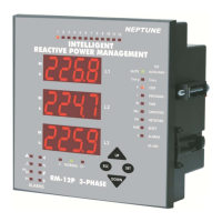
3.5.c Discharge Time Setting
By UP/DOWN buttons, select discharge time menu
(dELy t-on).
Press SET button to set discharge time (t-rC).
Enter a value between 1-1800 seconds and then press SET
butto. If you do not want to set another parameter, press ESC
button.
SAUE
If you do not want to set another parameter, in order to quit from the
menu, press ESC button one by one until SAVE SEt yES is displayed.
Press SET button to save your changes or press ESC button to quit
without saving.
3.6.a First Capacitor Step Setting
First capacitor step is used to find connection. For this reason, 3-phase
capacitor must be connected to the first step. So, connection setting for
first capacitor step is not possible and always RST connection type is
selected.
When setup parameter is selected as on in Auto menu, if any program
(except PS-10), is selected, power value of the first capacitor step is
measured and other steps power values are calculated according to
selected program. When Setup:of is selected, power values of all
capacitor steps (including first capacitor step) can be set manually.
Note : When setup parameter is selected as on in Auto menu, after
completing the measurement of capacitor powers according to the
selected program, RM-12P continues to work in setup:off mode.
In this menu, power values and connection types of all capacitor steps are
set.
There are 5 different connection types for capacitors which are R, S, T,
RST and off. Also capacitor step measurement for power values can be
set between 0,02-2,00. If off option is selected, there is no need to set
any power value.
Note : For first capacitor step, different connection type is impossible
andRST connection type always must be selected. Because first
capacitor step is used to detect correct connection.
Note : If PS-10 program is selected, capacitor powers can be set
separately for each capacitor step. However, if any program, except
PS-10, is selected, only first capacitor steps power value (C-01) can
be set manually. Capacitor powers for other steps are calculated
according to the selected program.
3.6 Connection Type and Power Value Settings
for Capacitors
By UP/DOWN buttons, select capacitor (CAP) menu. When
capacitor menu is displayed, capacitor (C/VAr) led ligths.
Press SET button for capacitor settings.
Press SET button for 3 sec. in order to enter to the menu.
3 sec.