225.5
228.7
223.4
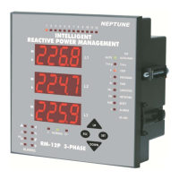
1.2 Front Panel
On the front panel, 3 display lines, 4 buttons and also alarm, capacitor
step and display leds exist. Measured parameters are observed in the
related displays. Displayed values for related parameters are selected via
indicator leds. When an alarm exists, related alarm led blinks. 12 capacitor
step leds indicates, which capacitor step is switched on. Detail information
about buttons, display, alarm and capacitor step leds will be explained
in the coming sections.
INTELLIGENT REACTIVE POWER MANAGEMENT
RM-12P
1.2.a Button Functions
UP
DOWN
ESC
SET
:
:
:
:
Go to next menu or increase related value.
Go to previous menu or decrease related
value.
Exit from a menu or cancel the data entry.
Enter to a menu or confirm the data entry.
1. INTRODUCTION
1.1 General Information
Power factor controllers are used for measurement and control of power
factor control units for central reactive power compensation. The power
factor, which is defined as ratio of active power (W) to apparent power
(VA), measured by power factor controller is compared with the set values
to provide necessary compensation.
RM-12P power factor controller is designed for reactive power compensation
in single phase and 3-phase systems.
RM-12P compensates each phase separately and so, this makes
RM-12P series a unique solution for unbalanced load compensation. In
order to perform this process, single phase and 3-phase capacitor steps
must be connected to the device at the same time.
Measured Parameters :
Phase Voltage (L
1,2,3
-N) Measurement
Phase Current (L
1,2,3
-N) Measurement
Cos
j
Value (L
1,2,3
-N) Measurement
Average (Ind./Cap.) Cos
j
Value Measurement
Active Power (W), Reactive Power (VAr), Apparent Power
(VA) Measurement
Total Active Power (Ind./Cap.), Total Reactive Power
(Ind./Cap.), Total Apparent Power (Ind./Cap.) Measurement
Active Energy (Wh-Import/Export), Reactive Energy
(VArh-Import/Export) Measurement
Measuring up to 19th Harmonic (V, I, W, VAr, VA)
1,3,5,.....,19
*Temperature Measurement
1)
2)
3)
4)
5)
6)
7)
8)
9)
*Optional
2
Type PR16
(144x144)
143
99
121
138.4
144
18
34.5
67
1) Panel cut-out dimension must be 139 mm x 139 mm
(Type PR16).
2) Before installation, remove the mounting brackets.
3) Mount the device to the front panel.
4) Insert the mounting brackets.
5) Wire thickness for voltage and current terminals must be
2,5 mm
2
.
6) CAT5 cable is recommended for RS-485 input terminal.
Excessive force can damage the device.
Turn the screw into the terminals and tighten until the
RM-12P is secured in place.
DIMENSIONS