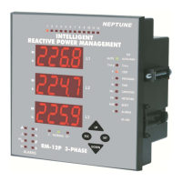
INTELLIGENT REACTIVE POWER MANAGEMENT
RM-12P
2. INSTALLATION
When RM-12P is powered-up for the first time, if the power value of
any phase is negative, RM-12P switches on&off the first capacitor step
automatically and it recognizes and records the connections.
Later, automatic setup (Refer to page 6 - Automatic setup) is selected
on the menu in order to automatic recognition of the connections and
connected capacitor steps.
After automatic recognition, RM-12P checks all capacitor step values.
If variable loads exist in the system, first of all these variable loads must
be disconnected and then automatic setup process must be done.
Otherwise, power factor controller may not measure capacitor step powers
correctly. Capacitor step powers and connection types also can be
recognized to the power factor controller manually.
(Refer to page 10 - Setting of the capacitors connection and power values)
After the recognition of capacitor step powers, target Cosj
value is set in order to start the compensation. Factory set value for target
Cosj is ind. 1.000 and Cosj2 is ind. 0.900
Note: PFC decreases the switching on&off time to 3 seconds in
Automatic Setup mode but discharge time is not changed. After the
automatic setup process, set values become valid.
Device finds connection errors and corrects automatically. Power
values of the capacitor steps are measured automatically according
to program selection. If PS-10 program is selected, power values of
all capacitor steps are measured (Refer to Program Section). If any
other program is selected, device measures first capacitor step value
and then calculates other capacitor steps according to the selected
program. For this reason,
a 3-phase capacitor must be connected to the first step. Then, single
phase and / or 3-phase capacitors can be connected with random
sequence to the other steps.
2.1 Commissioning
2.2 Capacitors Sequence
3. SETTINGS
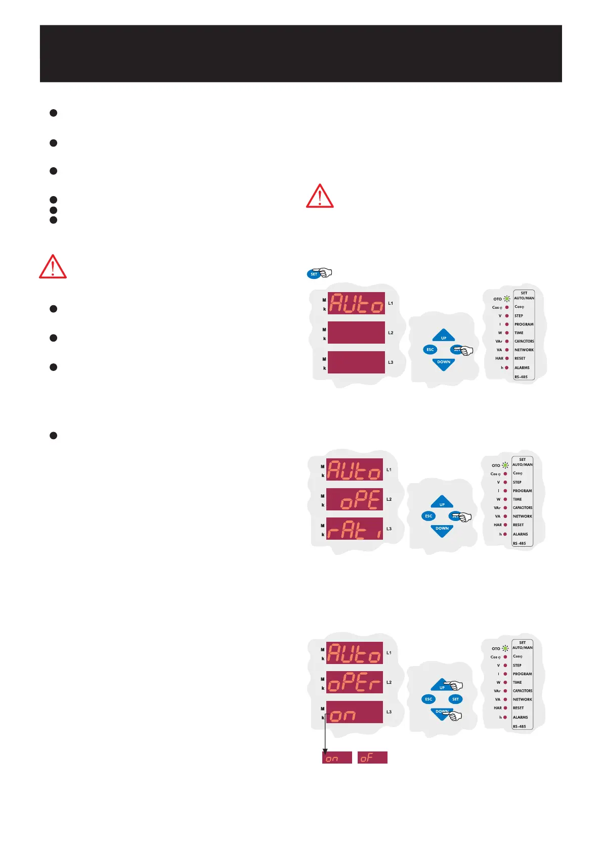
3.1.a Operating Mode Setting
RM-12P has two operating modes which are automatic and
manual. Manual mode is used for test purposes. In this mode,
capacitor steps are switched on&off to test relay outputs. In
manual mode, capacitor steps are switched on by SET
button and ESC button. Factory set values for switching on
(t-on) and switching off (t-of) time is 10 sec. These values can
be changed by the Delay menu (Refer to delay time setting).
In manual mode, step numbers, which will be switched on&off,
can be programmed in Step menu (Refer to step number
setting). Even if manual mode is selected, device switches to
automatic mode after 5 minutes.
When automatic mode is selected, AUTO/MAN LED lights on
continuously.
When manual mode is selected, AUTO/MAN LED blinks.
3.1 Operating Mode and Capacitor Power Settings
5
Press SET button for 3 sec. in order to enter to the menu.
Press SET button for parameter settings in Auto menu.
Press UP or DOWN button to select operating mode.
Press SET button to select the operating mode.
(on: Automatic Mode, of: Manual Mode).
Numerical values of the parameters are set via buttons in the
display. The blinking digit indicates which digit will be set.
Numerical value of the related digit is increased or decreased via
UP or DOWN button. To set the next digit, SET button is
used and also ESC button is used to set the previous digit.
Warning: Device warns user by blinking (short ON, long OFF)
led of the capacitor steps which will be switched on. Also
device warns user by blinking (long ON, short OFF) led of the
capacitor steps which will be switched off.
For proper operation, 3-Phase, neutral, voltage and current terminals
must be connected as in the connection diagram. Device does not work
properly without 3-phase connection.
The most important point is connecting 3-phase capacitor to the first
step. Remaining single phase and 3-phase capacitors can be connected
to the other steps.
After capacitor steps connection, if temperature measurement
function will be used, J-Type 0-400 V thermocouple must be connected.
(Temperature measurement feature is optional)
Lastly, computer communication connection must be done.
Do not power-up the device before verifying terminal connections.
To first step, always a 3-phase capacitor must be connected.
3 sec.
Warning: If fast load variation exists together with
compensation capacitors, device can not detect
correct connection at first time and may find after
several attempts. If device can not finish this
detection, C/k calculation can not be accomplished.