UPM 2000
Netech Corporation
110 Toledo St, Farmingdale, NY 11735
http://www.Netech.org
19
Overall Unit Layout
1-800-547-6547
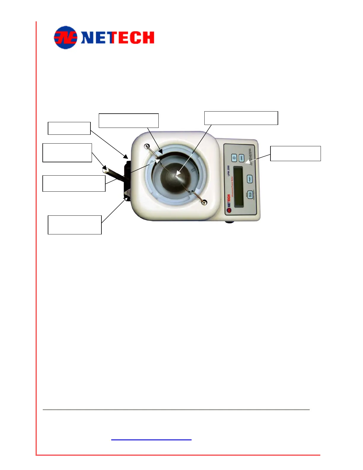
Figure 2-1: UPM 2000 General Layout
The top of the UPM 2000 Ultrasound Power meter is shown in Figure 2-1. It
includes the following components.
• Front Panel: Includes LCD readout and keyboard.
• Rear Panel: Includes Battery compartment, RS-232 Connector and
Power Transformer Jack.
• Sound Tank: To be filled with 600ml ± 50 ml of degassed and de-
ionized water for each use.
• Transducer Cone: The cone is removable for safe transporting.
• Leveling Bubble: Used to help level the unit before turning it on.
Leveling Jacks: Used to adjust the unit to a level position. (Figure 2-4)
• Universal Transducer Clamp Support Post: A removable vertically
mounted bar that the transducer clamp is attached.
Leveling
Bubble
Clamp
Support Post
Rear panel
Sound Tank
Transducer Cone
Front Panel
Cone Hanger