Security Gateway Manual Netgate-4200
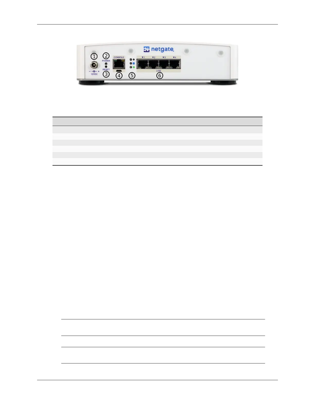
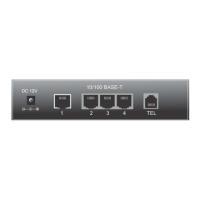
Fig. 12: Rear view of the Netgate 4200 Firewall Appliance
Item Description
1 Power Connector
2 ACPI Power Button (Protruding) - Graceful shutdown, hard power off (Hold 10s), power on
3 Reset Button (Recessed) - Used when performing the Factory Reset Procedure.
4 Serial Console (USB or RJ45)
5 Rear Status LEDs
6 Networking Ports
Power Connector (1)
The Power connector is 12VDC with threaded locking connector. Power consumption is approxi-
mately 13W when idle.
Power Button (2)
The upper protruding Power Button behaves the same as a typical ACPI power button.
If the device is powered on and running, pressing the button immediately performs a graceful shut-
down and the system enters a standby state.
If the system is in a powered off or standby state, pressing the power button immediately powers on
the device and starts the boot process.
If the system is unresponsive, holding in the power button for 10 seconds will forcefully power off
the device. Press the power button again to turn it back on.
Reset Button (3)
The lower recessed Reset Button is used to perform the Factory Reset Procedure.
Pressing and immediately releasing the button has no effect, it does not perform a hardware reset.
See Factory Reset Procedure for details on how to use the button to perform a factory reset.
Serial Console Port (4)
Clients can access the serial console using the USB Micro-B (5-pin) serial adapter port and a com-
patible USB cable or via the RJ45 “Cisco” style port with a separate cable and USB serial adapter or
client hardware port.
Note: Only one type of console connection will work at a time and the RJ45 console connection
has priority. If both ports are connected only the RJ45 console port will function.
Note: The serial console in the OS is a memory mapped serial port and not a traditional COM port.
pfSense
®
Plus automatically detects and uses the correct console type for this device.
© Copyright 2024 Rubicon Communications LLC 13