CHAPTER
THREE
REFERENCES
3.1 Switch Ports Overview
This document is an overview of how the switch operates and its capabilities.
For instructions on how to configure the switch in a variety of ways, including configuring the switch ports as isolated
independent interfaces, see Configuring the Switch Ports.
Warning: The switch is limited to a total maximum of 128 separate VLANs.
Warning: The switch ports do not support the Spanning Tree Protocol (STP). Two or more ports connected to
another Layer 2 switch, or connected to 2 or more different interconnected switches, could create a flooding loop
between the switches. This can cause the router to stop functioning until the loop is resolved.
3.1.1 Interface Links
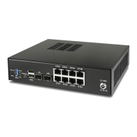
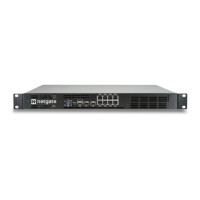
In addition to two SFP+ interfaces, there is also an Ethernet switch on the XG-7100. There are eight Ethernet ports on
this switch that are physically accessible – these interfaces are referred to as ETH1-ETH8. In addition to those 8 ports,
there are also three additional ports that operate behind the scenes - PORT 0, PORT 9 (ix2), and PORT 10 (ix3).
ETH1-ETH8 are gigabit switch ports.
PORT 9-10 are 2.5 Gbps uplink switch ports. These two ports connect the Ethernet switch to a Denverton SoC. The
SFP+ interfaces (ix0 and ix1) also connect to this SoC.
The diagram below demonstrates how these interfaces are connected:
75