16 • General Operation NEW FOCUS, Inc.
4.
Addressed
Indicator:
This indicator is lit whenever the controller
is communicating over the computer interface (see the “Computer
Control” chapter beginning on page 29).
5.
Remote
Indicator:
This indicator is lit whenever the controller is
under computer control, via either the IEEE-488 (GPIB) or the RS-
232 interface. (See “Computer Control” on page 29.)
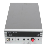
6. Power Keyswitch:
Controls AC power to the entire laser system,
including the temperature circuit in the laser head.
7.
Power
Button:
Turns on and off current to the laser diode.
8.
Mode
Button:
Switches the laser between constant-current and
constant-power modes (power to the laser diode must be off to
switch modes).
Constant-power mode requires an external beamsplitter and
photodetector. See the “Constant-Power Mode” chapter beginning
on page 25 for details.
9.
Display
Button:
Changes the display to show laser current, laser
power, piezo voltage, or auxiliary input voltage.
10.
Set Button: Activates/de-activates the adjustment knob so you can
adjust the displayed laser parameter (the properties you can
control depend on the operating mode).
11. Adjustment Knob: When activated by the Set button, this knob is
used for all adjustments of laser and system parameters.
12. Local Button: Returns the controller to local (front-panel) control
when the driver is in remote (computer) control.
13. GPIB Address Button: Displays the GPIB (IEEE) address setting. See
“Using the IEEE-488 Interface” on page 29 for more information.
14. Baud Rate Button: Displays the RS-232 baud-rate setting. See
“Using the RS-232 Interface” on page 30 for more information.
Vortex6000.book Page 16 Tuesday, February 19, 2002 3:25 PM
Artisan Technology Group - Quality Instrumentation ... Guaranteed | (888) 88-SOURCE | www.artisantg.com
 Loading...