GEO S12 HARDWARE SETUP PROCEDURE
Page 24 / 95 System Manual GEOS12 LS18
6.2 General Description
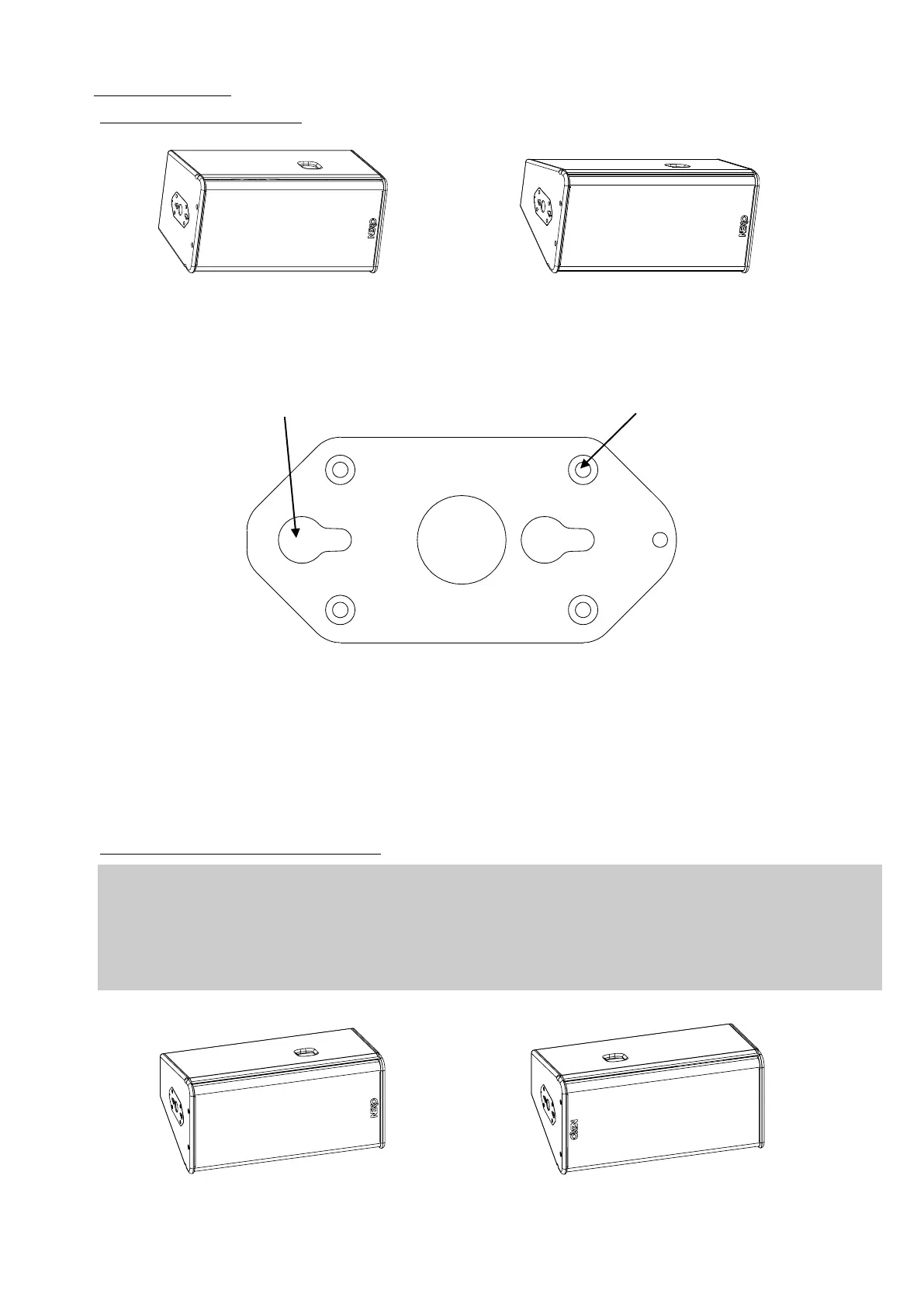
6.2.1 GEO S1210 and GEO S1230
GEO S1210 GEO S1230
GEO S1210 and GEO S1230 incorporate two connecting plates (one per side) on which a comprehensive range of accessories
can be mounted.
GEO S12 connecting plates
Angle splay setting sequences are as follow:
- GEO S1210 to GEO S1210: 0.2° / 0.31° / 0.5° / 0.8° / 1.25° / 2° / 3.15° / 5° / 6.25° / 8° / 10°
- GEO S1210 to GEO S1230: 16°
- GEO S1230 to GEO S1230: 16° / 22.5° / 30°
6.2.2 GEO S12 “Left” and “Right” configuration
GEO S12 can be installed “Left” or “Right”:
- “Left” means HF waveguide is left as seen from front
- “Right” means HF waveguide is right as seen from front
GEO S12 can be connected to bumpers “Left” or “Right” by simply flipping the cabinets.
Whenever possible, NEXO recommends symmetrical designs (preferably HF waveguide inwards in stereo
configurations)
GEO S12 “Left” GEO S12 “Right”
 Loading...

