GEO S12 GENERAL SET-UP INSTRUCTIONS
System Manual GEOS12 LS18 Page 9 / 95
2.1.3 Configuring GEO S12 for passive or active mode
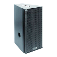
Remove the six TORX screws that hold the connector panel.
Remove the connector panel so that filter WAGO connectors become accessible.
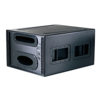
GEOS12 connector panel GEOS12 WAGO connectors
In Passive Mode, connector A (from filter) should be inserted in connector B (PCB “Passive In”), and connector D (“Passive
Out”) should be connected to speakers via connector C.
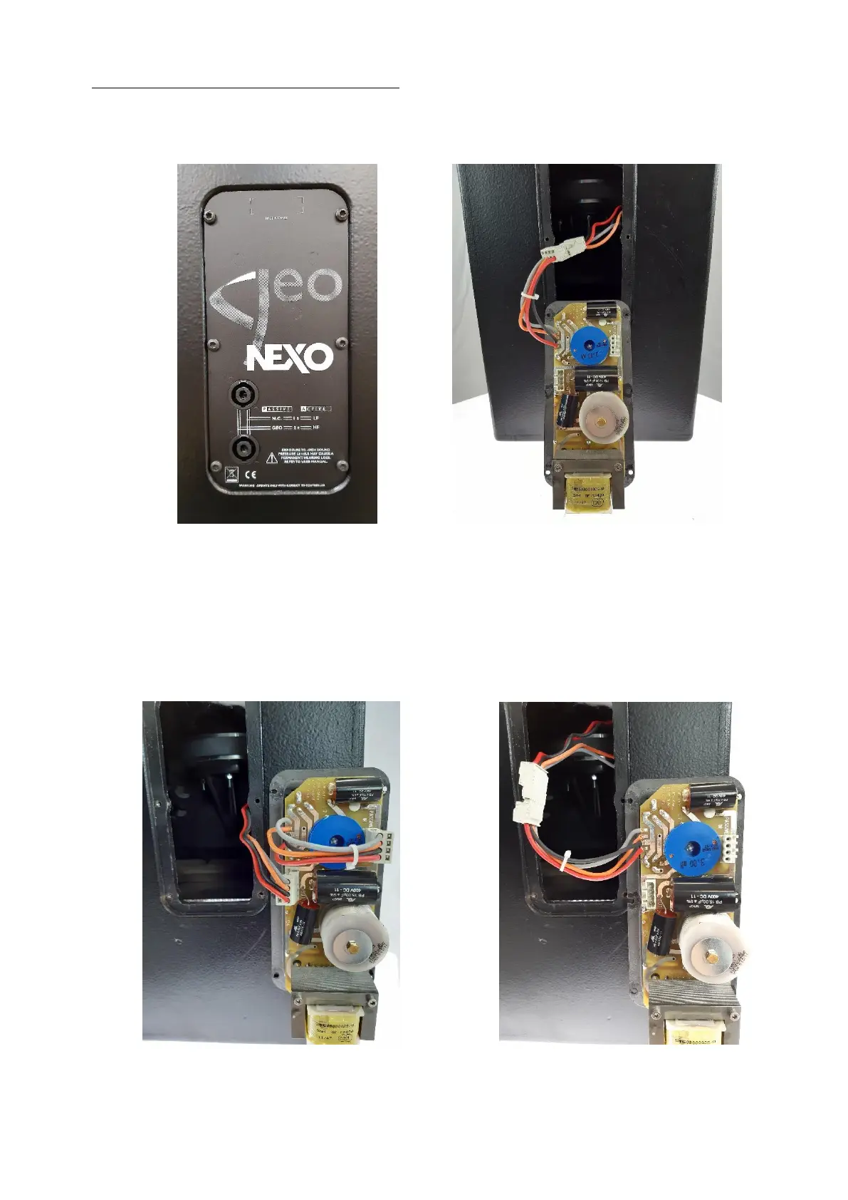
In Active Mode, WAGO Connector A (from filter) should be directly connected into speakers via connector C (PCB connectors
B & D are then unused).
Passive mode configuration Active mode configuration
 Loading...