GEO S12 HARDWARE SETUP PROCEDURE
System Manual GEOS12 LS18 Page 31 / 95
6.3.4 GEO S12 vertical array rigidly mounted on a ceiling
Required items
- 1 x GPI-BUMPER (allows +/-5° bumper tilt when installed below a flat surface; if higher bumper tilt is required, surface will
have to be defined accordingly)
- (N-1) x GPI-ANPL for a N x GEO S12 array (ANPL1 ranges from 0.2° to 3.15°, ANPL2 ranges from 5° to 10°, ANPL3 ranges
from 16° to 30°)
- 4 x 12mm diameter screws (not provided)
IMPORTANT
Ensure that the ceiling is strong enough to hold 4 times GEO S12 cluster weight and that the four screws
12mm diameter and corresponding plugs required to fix the bumper under the ceiling are properly
dimensioned.
Procedure
- Set all GEO S12 sideways according to cluster configuration
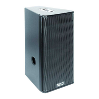
- Remove the four TORX screws holding connector plates on upper side of all GEO S12’s
- Remove the connector plates from all Geo S12’s
- Position bottom counter-plates, angle plates and top counter-plates from GPI-ANPL kit to required inter-cabinet angle value
between cabinets upper sides
- Use thread lock coated screws (or if not apply Loctite 243 or equivalent to shoulder screws) from GPI-ANPL kits
- Screw shoulder screws so that all plates and cabinets are tightened together
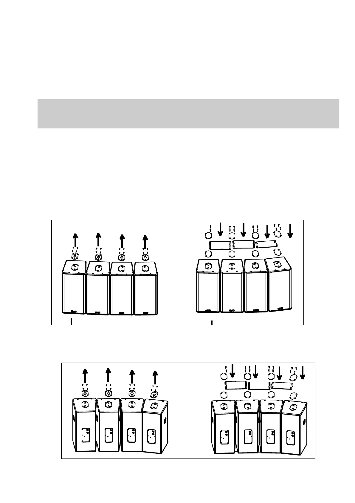
- Flip the cluster upside down to access connector plates located on the down side
- Repeat all above steps
 Loading...

