GEO S12 HARDWARE SETUP PROCEDURE
Page 52 / 95 System Manual GEOS12 LS18
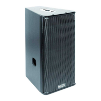
- Insert GPT-XBOW into connecting plates of both sides of GEO S12s
GEO S12 XBOW ANGLE SETTINGS PLATE
- Lock safety pins into LS18 and GEO S12s connecting plate
IMPORTANT
Ensure that safety pins are properly locked into LS18s and GEO S12s connecting panels.
- Connect bumper to first LS18 or GEO S12 using “lift” points of XBOWs
- Ensure quick release pins are properly locked
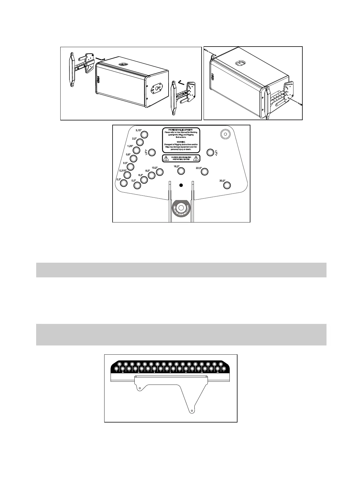
- Insert axis in bumper NS-1 predefined hole and secure it with provided “R” clip
Bumper holes are numbered #-17 to #17, please refer to NS-1 to determine axis position in relation to
bumper angle requirements.
If bumper is flown with 2 hoists, then they should be connected to holes #-17 and #17.
- Connect hoist hook to bumper axis and lift assembly to sufficient height in order to connect a second LS18 or GEO S12
- Connect second LS18 or GEO S12 with X-Bow front articulation holes and rear link bars and ensure quick release pins are
properly locked
 Loading...

