Ventilation connection
FIGHTER 200P
For the Installer
12
FIGHTER 200P is connected so that all ventilation air
except the kitchen fan passes the evaporator (62) in
the heat pump. The lowest ventilation flow according
to current standards is 0.35 l/s per m
2
floor area. For
optimum heat pump performance this ventilation flow
should not be less than 100 m
3
/h. (28 l/s).
FIGHTER 200P is equipped with a ventilation opening
in the base. As a result, an air flow of about 5 m
3
/h
(1,4 l/s) is taken directly from the room where the heat
pump is installed. Changing the ventilation capacity is
described under “Electrical connection - Setting the
fan capacity”. See also “Circuit diagram”. The curve’s
designation refers to the position of the knobs on the
circuit board for fan speed (158).
FIGHTER 200P gives the possibility to connect a
two way switch for choosing between normal ventila-
tion and reduced ventilation. The reduced ventilation
should only bee chosen when no one is at home.
To obtain the necessary air exchange in every room
of the house, the exhaust air devices must be correc-
tly positioned and adjusted. An incorrect ventilation
installation may lead to reduced heat pump efficiency
and thus poorer operating economy, and may result in
damage to the house.
NOTE!
A duct in a masonry chimney stack
must not be used for extract air.
To prevent fan noise being transferred to the exhaust air
devices, it may be a good idea to install a silencer in the
duct. This is especially important if there are exhaust air
devices in bedrooms. Because the heat pump contains a
flammable refrigerant in the form of propane (R290), the
air ducting system must be earthed. This is done by mak-
ing a sound electrical connection to the exhaust air duct
and extract air duct using the two earthing cables sup-
plied. The cables must then be connected to the earthing
studs on top of the top cover.
Duct connections should be made via flexible hoses,
which must be installed so that they are easy to replace.
The extract air duct is to be insulated using diffusion-proof
material along its entire length. Provision must be made
for inspection of the duct. The exhaust air duct should be
fitted with an adjustment damper. Make sure that there
are no reductions of cross-sectional area in the form of
creases, tight bends etc, since this will reduce the ven-
tilation capacity. All joins in the ducting must be sealed
and pop-riveted to prevent leakage.
The air duct system should, at a minimum, be of air tight-
ness class B.
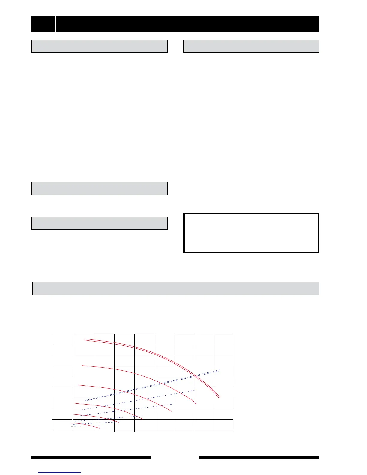
The diagram below shows the available ventilation
capacity.
Fan diagram
Ventilation flow Duct installation
Adjustment
The kitchen duct must not be connected to FIGHTER
200P.
Kitchen duct