Electrical connection 13
For the Installer
FIGHTER 200P
Disconnect the heat pump before insulation testing the
house wiring.
The supply (230 V~ 1-phase + N) for the heat pump
must be connected to terminal (9) via a cable clamp.
The connection of the heat pump must be done under
the supervision of a qualified electrician.
The heat pump installation implies a contact breaker.
The vinyl-pipe on the right side may be used as cable
entry conduit.
The temperature limiter (6) cuts off the supply to the
immersion heater if the temperature rises to 88 °C; it
can be manually reset by pressing the button on the
temperature limiter.
The temperature limiter (7) for the compressor cuts off
the supply to the compressor if the temperature rises
to 88 °C; it can be manually reset by pressing the but-
ton on the temperature limiter.
Connection
NOTE!
Reset the temperature limiter,
it may have tripped during transport.
NOTE!
The switch (8) must not be moved
from “0” until the boiler has been
filled with water Otherwise the tem-
perature limiter, thermostat, compres-
sor and the immersion heater can be
damaged.
NOTE!
The electrical installation, wiring and
any service work must be done in strict
conformity to current regulations
under the supervision of a qualified
electrician.
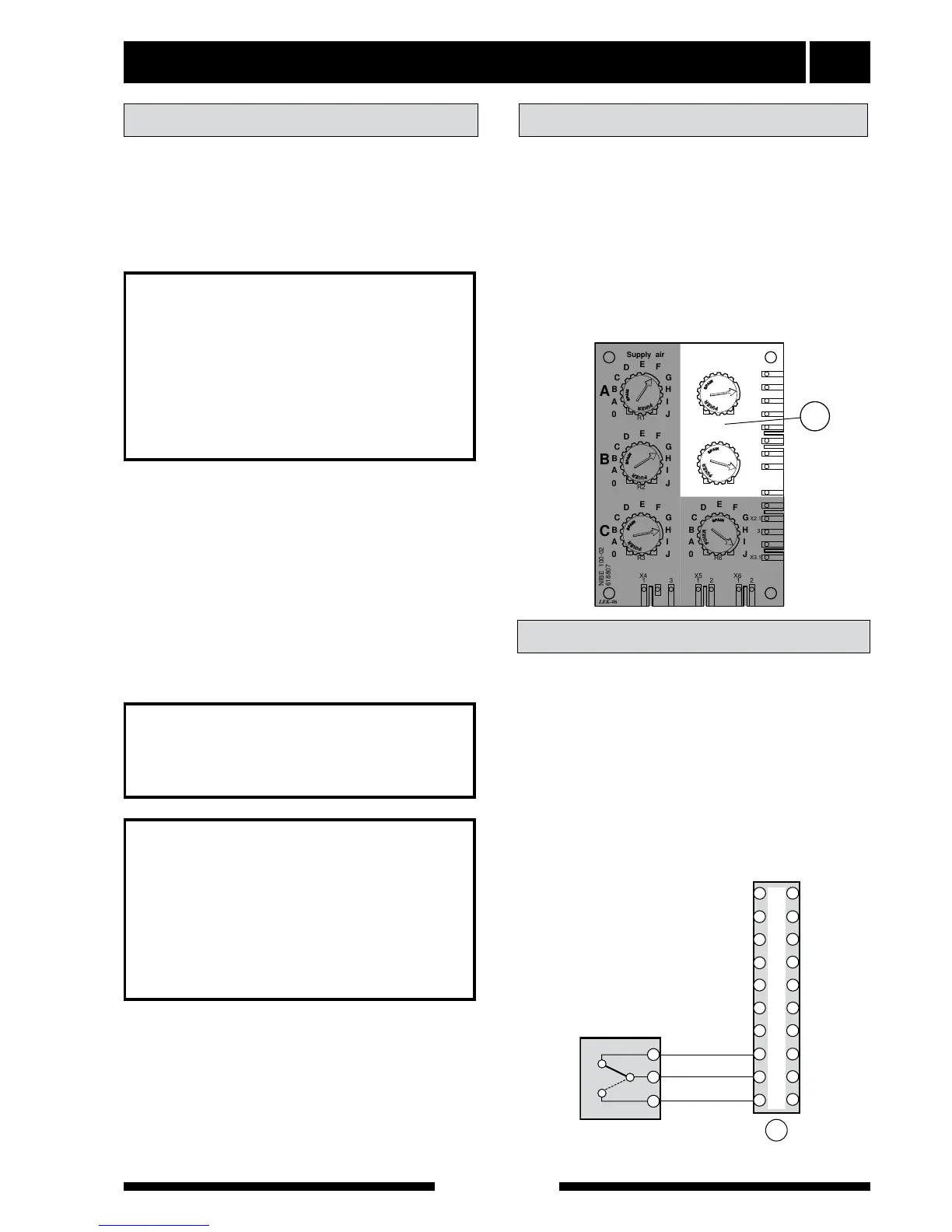
Setting the fan capacity
Selection of the exhaust fan capacity is done by tur-
ning the knobs on card (158) to the required settings.
See diagram "Ventilation connection" – "Fan diagram".
Positions as follows:
Knob A (”Exhaust air”): Reduced (if two way switch is
mounted)
Knob B (”Exhaust air”): Normal
Knob C (”Exhaust air”): Not used
Knobs under "Supply air" are not used.
FIGHTER 200P gives the possibility to connect a two
way switch for choosing between normal ventilation
and reduced ventilation.
■ Remove the strapping from terminal (11) position
"8" and "9".
■ Connect the fan switch on terminal (11) as illustra-
ted.
A closed circuit between position "8" and "9" results in
normal fan speed.
A closed circuit between position "10" and "9" results
in reduced fan speed.
Connecting a fan switch