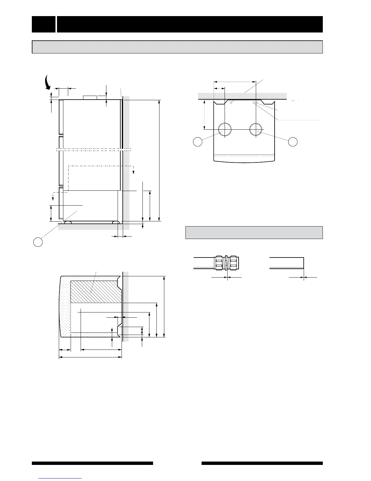
Dimensions
FIGHTER 200P
For the Installer
24
Dimensions and setting-out coordinates
A, B och C ska vara 100 % Röd
och 100 % Gul i PB
Undvik rördragning inom streckmarkerat
område för att underlätta service
Skyddsklenspänning Ø 16
Frånluft Ø 125
Avluft Ø 125
Elektrisk
matning Ø 25
Dockning Ø 16
91 90
A 15
Ställbar 15 – 40
250
45
Min avstånd
10 mm från vägg
Lucka på
båda sidor
Erforderligt utrymme för
demontering av övre frontlucka
77
B
615
115
C
355
600
2095
440
115
295
70
35
40
20
35
70
A, B and C: see "Connection" in "Component list".
Pipes must not be run from the floor in the area indi-
cated by dots.
A clear space of 500 mm is
needed in front of the heat
pump for servicing.
Principle of dimensioning
Space required for removal of
upper front access panel
Minimum distance
from wall 10 mm
Safety low voltage ø 16
Electrical feeding ø 25
Docking ø 16
Exhaust air ø 125
Vented air ø 125
Compression ring
Copper pipe
Access panel on
both sides
When running pipes in the hatched area
to facilitate servicing.
Adjustable 15-40