9NIBE VVM 300
User guide
Dealing with malfunctions
In the event of malfunction or operating disturbances first
check the points below:
Low temperature or a lack of hot water
Q Air in boiler or system.
Q Large amounts of hot water were used.
Q Circuit or main MCB tripped.
Q Possible earth circuit-breaker tripped.
Q Mixer valve set too low (45).
Q Switch (8) set to “0”.
Q Tripped Miniature circuit-breaker (7) or Fine-wire fuse
(33). See “Dealing with malfunctions” – “Resetting the
miniature circuit breakers”.
Q Tripped temperature limiter (6). (Contact service)
Q Closed or throttled filler valve (46) to the heater.
Q External control may have blocked the electrical out-
put.
Q Incorrectly set values for hot water production.
High hot water temperature
Q Mixer valve set too high.
Q Incorrectly set values for hot water production.
Low room temperature
Q Air in boiler or system.
Q Circuit or main MCB tripped.
Q Possible earth circuit-breaker tripped.
Q Tripped Miniature circuit-breaker (7) or Fine-wire fuse
(33). See “Dealing with malfunctions” – “Resetting the
miniature circuit breakers”.
Q Tripped temperature limiter (6). (Contact service)
Q Automatic heating control system settings not correct.
Q 24 hour setting incorrectly set so that night reduction is
active during the day.
Q Circulation pump (16) stopped. See the section
“Dealing with malfunctions” – “Starting the pump”.
Q Close valves (44) and (50) in the radiator circuits.
Q Initial pressure in expansion vessel too low. This is
indicated by low pressure on the pressure gauge (42).
Contact the installer.
Q External control may have blocked the electrical out-
put.
High room temperature
Q Incorrect values set on the automatic heating control
system.
If the operating disturbance cannot be rectified by means
of the above an installation engineer should be called.
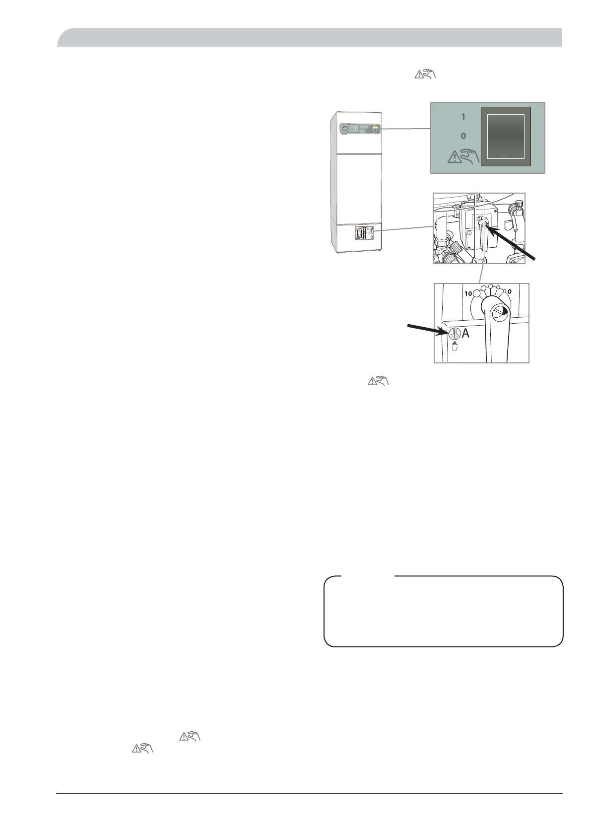
If necessary set the switch to”
”. See the section,
“Switch position “
”.
The adjustment
screw
Switch position “ ”
In mode ” ” the boiler’s electronic controls are dis-
connected, the display window is not lit.
The immersion heater is controlled by a separate thermo-
stat. Available output in standby mode is 4 kW.
The automatic heating control system is not operational,
so manual shunt operation is required. This is done by
turning the adjustment screw to “manual mode” and then
turning the shunt knob to the desired position.
The circulation pump (16) and charge pump (40) are in
continuous operation.
When returning to normal mode do
not forget to reset the shunt knob to its
original position by turning the adjustment
screw to “A”.
NOTE!
LEK
+
2
0
-2
A
B
A
B
A
B
I
I
I
I
I
I
I
I
I
I
I
I
V
V
M
300
 Loading...