+HDWFXUYH
7NIBE VVM 300
User guide
Room temperature
15 14 13 12 11 10
9
8
7
6
5
4
3
2
1
- 40
UTETEMPERATUR
- 10
0
10
- 5
+ 5
30
40
50
60
70
FRAMLEDNINGSTEMPERATUR
- 20 - 30
FÖRSKJUTNING
-
VÄRMEKURVA
30
40
50
60
70
- 40
UTETEMPERATUR
- 10
0
10
- 20 - 30
15 14 13 12 11 10 9
8
7
6
5
4
3
2
1
VÄRMEKURVA
- 5
+ 5
FÖRSKJUTNING
1514 13 12 11 10
8
7
6
5
4
3
2
1
- 40
UTETEMPERATUR
- 10
0
10
- 5
+ 5
30
40
50
60
70
FRAMLEDNINGSTEMPERATUR
- 20 - 30
FÖRSKJUTNING
9
VÄRMEKURVA
“Heating curve” in menu 2.1 and “Max sup-
ply temp.” in menu 2.4 are adjusted accord-
ing to the heating system in
question.
NOTE!
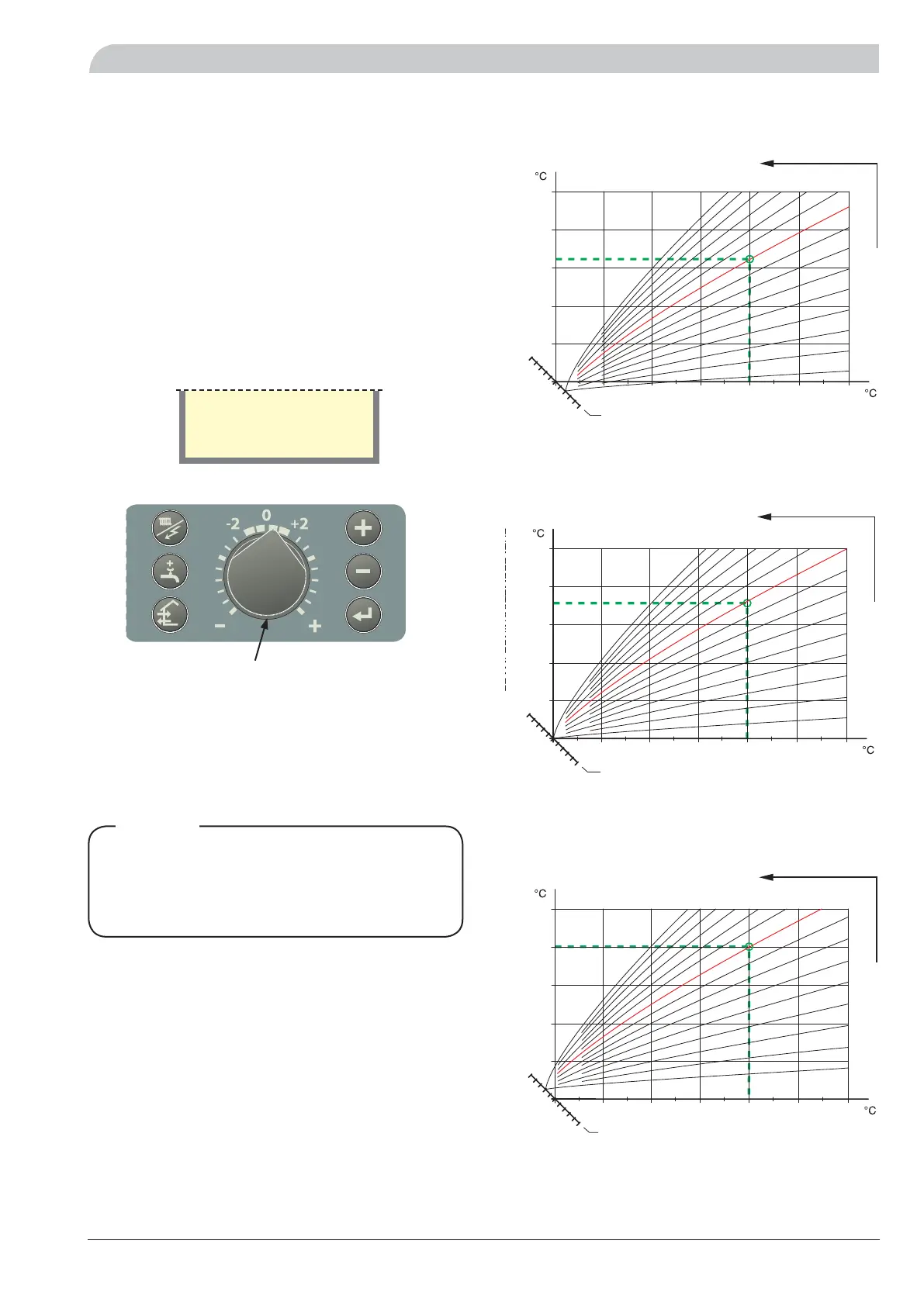
Setting with diagrams
The heating control system on VVM 300 is controlled by
the outside temperature. This means the flow temperature
is regulated in relation to the current outdoor temperature.
The diagram is based on the dimensioned outdoor temper-
ature in the area and the dimensioned supply temperature
of the heating system. When these two values “meet”,
the heating control's curve slope can be read. This is set
under menu 2.1, “Heating curve”.
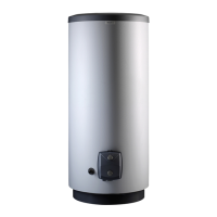
A suitable value is set using the knob on the front panel,
“Offset heat curve”. A suitable value for underfloor heat-
ing is -1 and for radiator systems -2.
Offset heating curve
Menu 2.1 Heat curve
Shifting the heating curve -2
HEATING CURVE
OFFSET HEAT CURVE
SUPPLY TEMPERATURE
OUTSIDE TEMPERATURE
Shifting the heating curve 0
HEATING CURVE
OFFSET HEAT CURVE
SUPPLY TEMPERATURE
OUTSIDE TEMPERATURE
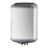
+($7,1*&859(
6833/<7(03(5$785(
2876,'(7(03(5$785(
2))6(7+($7&859(
Shifting the heating curve +2