4 NIBE VVM 300
User guide
2
1
bar
3
04
A B A B A BI II III
54.1°C
Hotwatertemp.
1.0
13.43
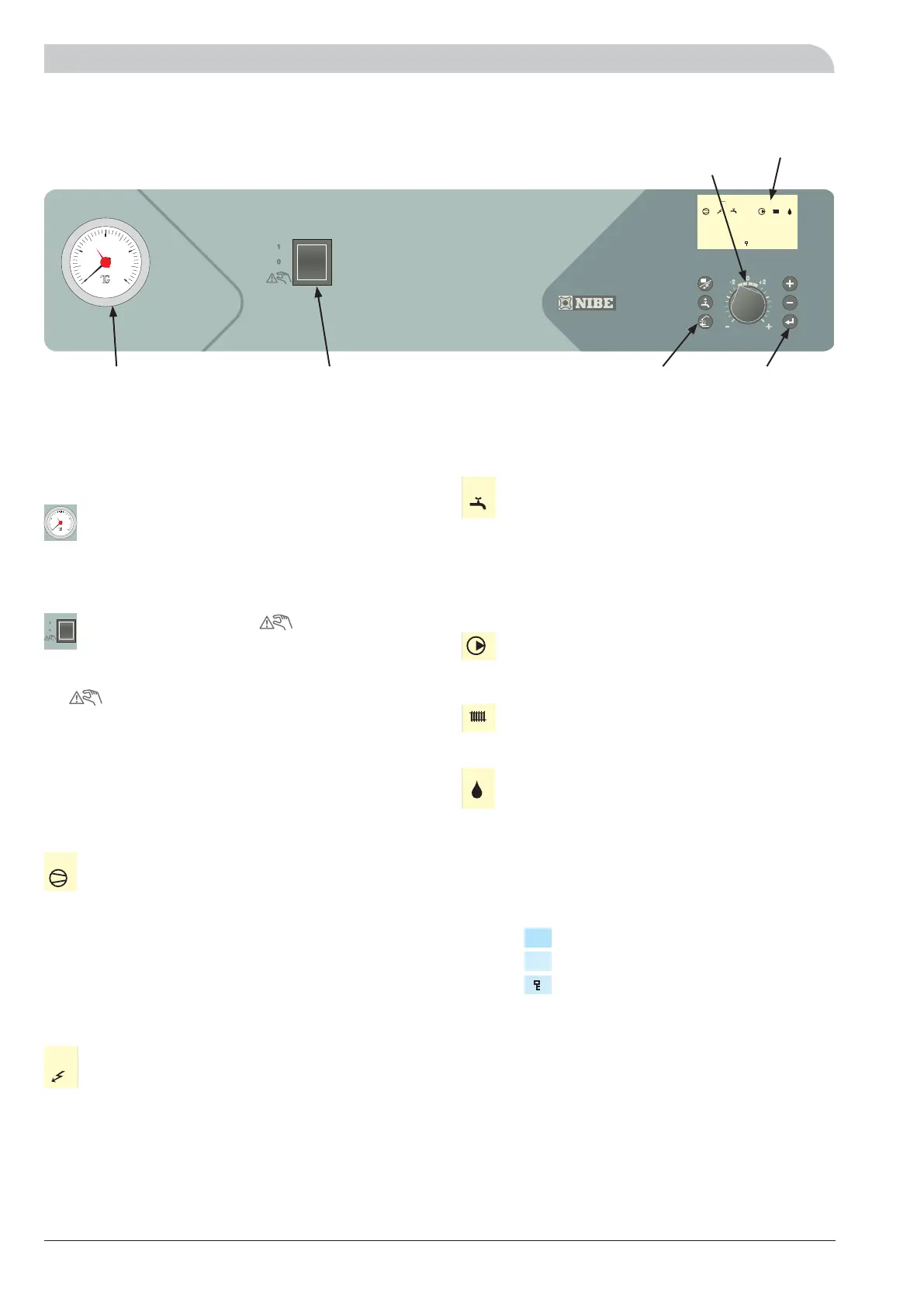
Front panel
Front panel
Display
Right keypadLeft keypad
Offset heating
curve
with three positions 1 – 0 – :
1 Normal mode. All control functions connected.
0 The boiler is completely switched off.
Standby mode. This mode is used in the event
of operating disturbances. The immersion
heater output is limited to 4 kW, the circula-
tion pump (16) and charge pump (40) operate
continuously.
Compressor symbol
A together with compressor symbol, is displayed
when fan step 1 is in operation.
B together with compressor symbol, is displayed
when fan step 2 is in operation.
The compressor symbol alone indicates that the
compressor is to start, but is locked due to start
conditions in the F20XX not being met internally,
e.g. time conditions.
Addition. heat symbol
Indicates when the additional heater is connected.
The line indicates which power step/steps are cur-
rently connected.
I 2 kW additional power is connected.
II 4 kW additional power is connected.
Switch
Hot water symbol
Indicates when the “Extra hot water” function is
active.
A is shown when 3 hour temperature increase is
activated.
B is shown when a time based temperature in-
crease is activated, for example periodic.
Circulation pump symbol
Shown when the circulation pump in the heating
system is in operation.
Heating system symbol
Shown when house heating with heat pump is in
progress.
Defrosting symbol
Indicates when F20XX defrosting is in progress.
Display
First row:
Second row: Value of the current parameter.
Third row: Description of current display parameter.
“Hot water temp” is normally shown.
Fourth row: Shows information symbols.
Menu number.
Pool heating in progress.
Key lock activated.
Switch
Pressure gauge
The radiator circuit pressure is displayed here.
Gauge graduation is 0 – 4 bar. Normal pressure is
0.5 – 1.5 bar when the system is closed.
Pressure gauge
A B
A B
2
1
bar
3
04
I II III
1.0
P
 Loading...