21NIBE VVM 300
Installation
Electrical connections
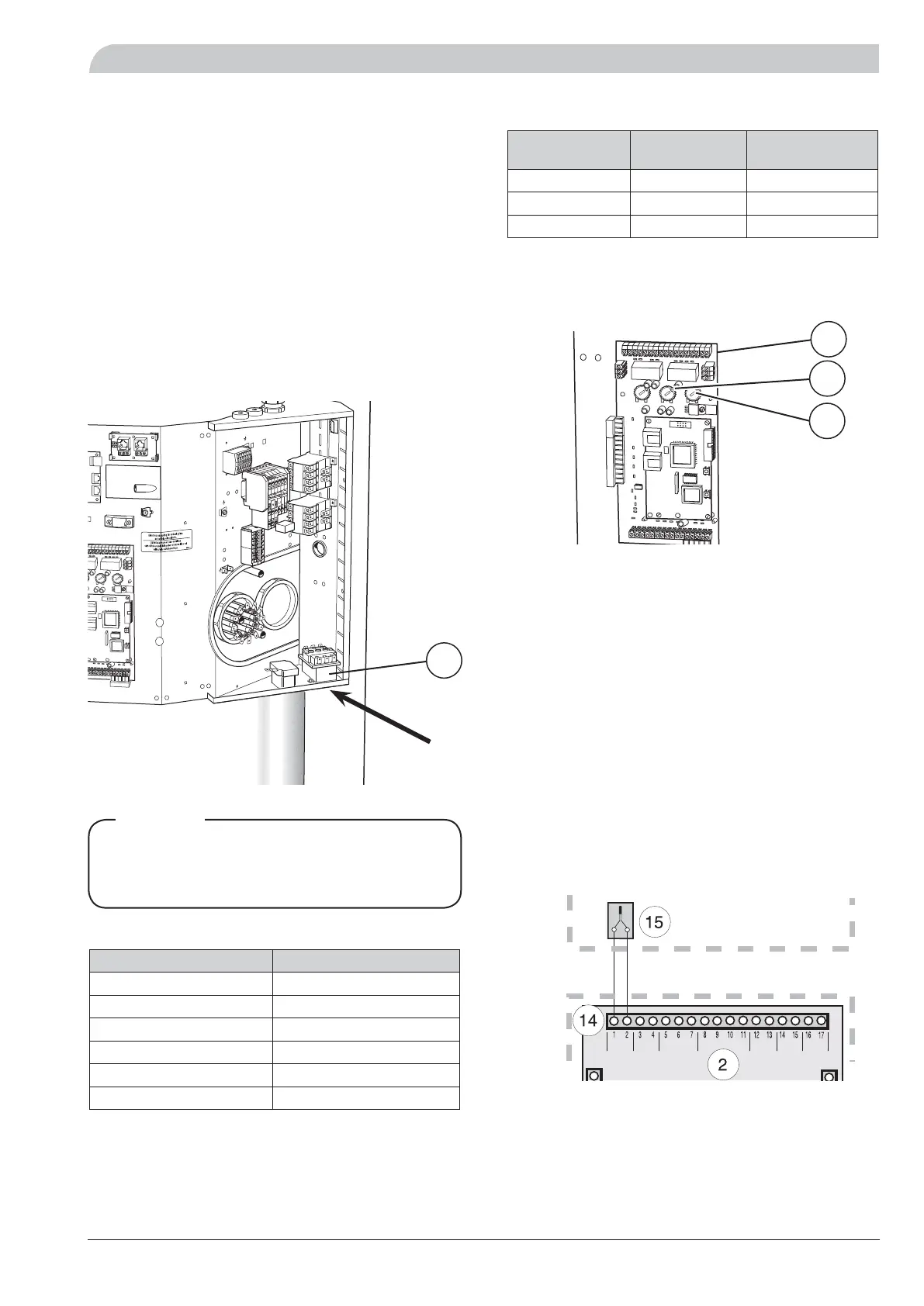
Connecting the outside sensor
Install the outside sensor in the shade on a wall facing
north or north-west, so it is unaffected by the morning
sun. The sensor is connected with a two-wire cable to
terminal block (14) positions 1 and 2, on the load monitor
card (2).
If a conduit is used it must be sealed to prevent condensa-
tion in the sensor capsule.
The minimum cable cross section should be 0.4 mm
2
up to
lengths of 50 metres, for example, EKKX or LiYY.
NOTE! To prevent interference, sensor cables and commu-
nication cables must be separated (min 20 cm) from high
voltage cable when cable routing.
Power rating as set at the factory
The immersion heater has a total maximum output of
6.0 kW. The power rating as set at the factory is 6.0 kW,
which corresponds to position C on the knob (101) on the
load monitor card (2).
Resetting the temperature limiter
The temperature limiter (6) is accessible from behind the
centre front cover and is positioned under the inner pro-
tective cover.
The temperature limiter is reset by firmly pressing in its
button. The button can be accessed from the underside
of the distribution box. The cover on the distribution box
does not need to be removed when resetting.
Work behind covers secured by screws may
only be carried out under the supervision of
a qualified installation engineer.
NOTE!
Max boiler temperature
Boiler temperature Knob position
55 A
60 B
65 C
70 D
75 E
80 F
The setting of the different maximum boiler temperatures
is done using the knob (102) on the load monitor card (2).
Set value displayed in menu 9.3.1.
Max phase current
Immersion hea-
ter, output (kW)
Knob position Max load phase
(A)
2.0 A 9.2
4.0 B 17.9
6.0 C 26.6
The setting of the different maximum immersion heater
outputs is done using the knob (101) on the load monitor
card (2). Set value displayed in menu 8.3.2.
6
2
101
102
 Loading...