19NIBE VVM 300
Installation
Electrical connections
Connection
VVM 300 must be installed via an isolator switch with a
minimum breaking gap of 3 mm. When the building is
equipped with an earth-fault breaker, VVM 300 should be
equipped with a separate one. Other electrical equipment,
except the outdoor sensor and the current sensors, are
connected at the factory.
Disconnect the electric boiler before insulation testing the
house wiring.
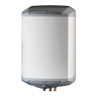
Electrical connections
The electric boiler is connected by the protruding cable via
circuit breaker. Connection must not be carried out with-
out the permission of the electricity supplier and under the
supervision of a qualified electrician. The cable entry con-
duit is dimensioned for cable with a max Ø 19 mm.
The power is controlled via a contactor which is operated
by a microprocessor.
The temperature limiter (6) cuts off the supply to the im-
mersion heater if the temperature rises to between 90 and
100°C; it can be manually reset by pressing the button on
the temperature limiter.
The switch (8) must not be moved from “1”
or “ ” until the boiler has been filled
with water. Otherwise the temperature
limiter, thermostat, compressor and the
immersion heater can be damaged.
NOTE!
Reset the temperature limiter, it may have
tripped during transportation.
NOTE!
The automatic heating control system, circulation pump
(16), charge pump (40) and its cabling, are internally fuse
protected with a miniature circuit breaker (7).
Electrical installation and service must
be carried out under the supervision of a
qualified electrician. Electrical installation
and wiring must be carried out in accord-
ance with the stipulations in force.
NOTE!
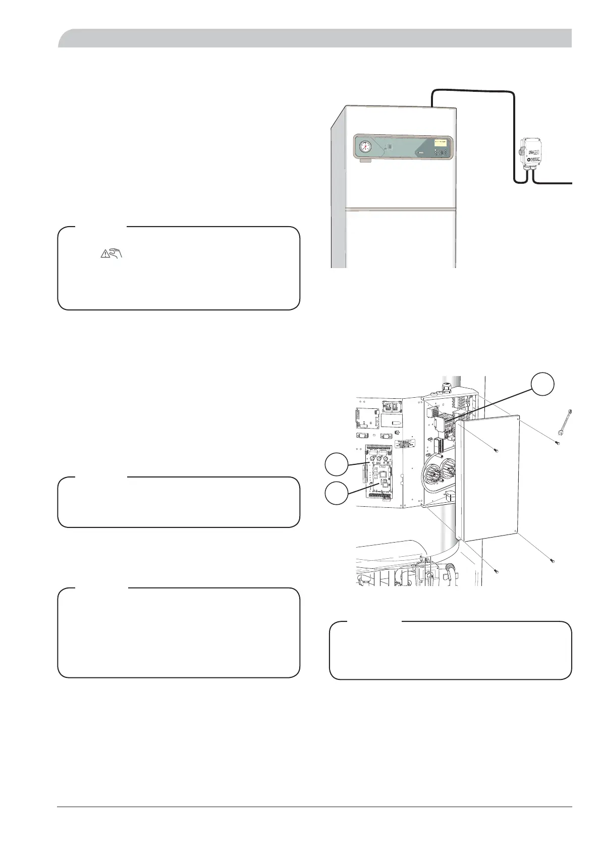
Access to the lower electrical connections
Remove the upper and lower front cover. Open the centre
front cover by removing the two screws at the lower edge.
The load monitor card (2) and CPU card (34) can now be
accessed on the left-hand side. Remove the protection
plate by loosening the four screws to gain access to the
right-hand side.
Work behind covers secured by screws may
only be carried out under the supervision of
a qualified installation engineer.
NOTE!
+2
0
-2
A
B
A
B
A
B
I
II
II
I
I II
I
I
I
VVM 300
10
10
VAN
A
D
I
UM
N
o
.
7
CHR
OME
2
9
34

 Loading...