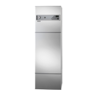
1NIBE VVM 300
User guide
General
Principle of operation ______________________________ 3
System diagram ___________________________________ 3
Abbreviations _____________________________________ 3
Front panel
Pressure gauge ____________________________________ 4
Switch ___________________________________________ 4
Display ___________________________________________ 4
Offset heating curve _______________________________ 5
Right keypad _____________________________________ 5
Left keypad _______________________________________ 5
Key lock _________________________________________ 5
Room temperature
Heating control system _____________________________ 6
Default setting ____________________________________ 6
Changing the room temperature manually ____________ 6
Setting with diagrams ______________________________ 7
Maintenance routines
Checking the safety valves __________________________ 8
Pressure gauge ____________________________________ 8
Low temperature or a lack of hot water _______________ 9
High hot water temperature _________________________ 9
Low room temperature _____________________________ 9
High room temperature ____________________________ 9
Switch position “
” ___________________________ 9
Alarm/alarm outputs ______________________________ 10
Resetting the temperature limiter ___________________ 12
Helping the circulation pump to start ________________ 12
Resetting the miniature circuit breakers ______________ 12
Installation
General information for the installer
Transport and storage _____________________________ 13
Maximum boiler and radiator volumes _______________ 13
Erecting the heat pump ___________________________ 13
Inspection of the installation _______________________ 13
Electric boiler mode _______________________________ 13
Pipe connections
General _________________________________________ 14
Pipe connection of the heating system and hot water __ 14
Docking_________________________________________ 15
Pipe connection between VVM 300 and F20XX _______ 17
Capacity diagram, heating medium pump ____________ 17
Capacity diagram, charge pump ____________________ 17
Service
Draining the heating system ________________________ 18
Emptying the hot water heater _____________________ 18
Contents
Electrical connections
Connection ______________________________________ 19
Access to the lower electrical connections ____________ 19
Communication cable between VVM 300 and F20XX __ 20
Power rating as set at the factory ___________________ 21
Resetting the temperature limiter ___________________ 21
Max boiler temperature ___________________________ 21
Max phase current ________________________________ 21
Connecting the outside sensor______________________ 21
Centralised load control/Tariff ______________________ 22
External contacts _________________________________ 23
Commissioning and adjusting
Preparations _____________________________________ 24
Filling the hot water heater and the heating system ____ 24
Venting the heating system ________________________ 24
Commissioning F20XX and VVM 300 ________________ 25
Commissioning VVM 300 without F20XX ____________ 25
Readjustment ____________________________________ 25
Miscellaneous
Control
General _________________________________________ 26
Key lock ________________________________________ 26
Quick movement _________________________________ 26
Changing parameters _____________________________ 27
Example ________________________________________ 27
Menu explanation
Main menus _____________________________________ 32
1.0 Hot water temp. ______________________________ 33
2.0 Supply temp. _________________________________ 34
3.0 Supply temp. 2* ______________________________ 35
4.0 Outdoor temp. _______________________________ 36
5.0 Heat pump ___________________________________ 36
6.0 Room temperature* ___________________________ 37
7.0 Clock _______________________________________ 38
8.0 Other adjustments ____________________________ 39
9.0 Service menus ________________________________ 40
Electrical circuit diagram
Sensor placement ________________________________ 51
Temperature sensor data ___________________________ 51
Technical specifications
Component locations _____________________________ 52
List of components _______________________________ 53
Dimensions and setting-out coordinates ______________ 54
Measuring principle _______________________________ 54
Accessories ______________________________________ 55
Technical specifications ____________________________ 56
Enclosed kit _____________________________________ 56

 Loading...