English – 1
ENGLISH
Safety warnings
• IMPORTANT! – This manual contains important instructions and warn-
ings for personal safety. Incorrect installation could cause serious physical
injury. Read all parts of the manual carefully before starting work. If in doubt,
interruptinstallationandcontacttheNiceServiceCentreforclarications.
• IMPORTANT! – Important instructions: keep this manual in a safe place
to enable future product maintenance and disposal procedures.
Installation warnings
• Before commencing installation, check that the product is suitable for the
intended kind of use (see paragraph 2.2 “Limits of use” and chapter “Product
technicalspecications”).Ifnotsuitable,doNOTproceedwithinstallation.
• During installation, handle the product with care, avoiding the risk of crush-
GENERAL SAFETY WARNINGS AND PRECAUTIONS
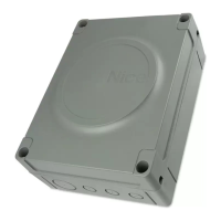
The MC424L control unit has been designed to control Wingo, Too, S-fab 24 V
electromechanical actuators, for automated swing gates or doors.
IMPORTANT! – Any uses other than those specied herein or in envi-
ronmental conditions other than as stated in this manual are to be con-
sidered improper and are strictly prohibited!
The MC424L control unit operates on the basis of a current sensitivity system
which checks the load of the motors connected to it. The system automatically
detects travel stops, memorises the running time of each motor and recognises
obstacles during normal movement. This feature makes installation easier as
there is no need to adjust the working times nor the leaf delay.
The control unit is pre-programmed for the functions usually required and
incorporates a radio receiver for the remote controls. Using a simple procedure
itisalsopossibletochoosemorespecialisedfunctions(seechapter5).
The control unit is provided with a type SM socket for plug-in radio receivers
(see paragraph "6.1 - Connection of a radio receiver") and a type IBT4N socket
which, through the IBT4N interface, allows BusT4 devices to be connected as
well as the Oview programming unit (see paragraph "6.2 - Connection of IBT4N
interface").
The control unit is set up to be powered by PS124 back-up batteries as an
emergency power supply, in the event of a power cut (see paragraph "6.3 -
Connection of back-up battery mod. PS124"); it is also set up to be connected
to the "Solemyo" solar energy power supply system (see paragraph "6.4 - Con-
nection of Solemyo system").
PRODUCT DESCRIPTION
1
In order to explain certain terms and aspects of an automatic 2-leaf swing door
or gate system refer to the typical system shown in g 1.
Key to g. 1:
1. Wingo, Too, S-fab 24 V electromechanical actuator
2. Wingo, Too, S-fab 24 V electromechanical actuator
3.Lucy24ashinglight
4. Key-operated selector switch
5. “PHOTO” pair of photocells
6. “FOTO1” pair of photocells
7. “PHOTO2” pair of photocells
8. Control unit.
In particular, please note that:
• Refer to the product instructions for the characteristics and connection of the
photocells.
• Activation of the “PHOTO” pair of photocells have no effect on the gate dur-
ing opening, while they reverse movement during closing.
• Activation of the “PHOTO 1” pair of photocells stops both the opening and
closing manoeuvres.
• Activation of the “PHOTO2” pair of photocells (connected to the suitably pro-
grammed AUX input) has no effect during closing while they invert movement
during opening.
INSTALLATION
2
Translation of the original instructions
Summary
GENERAL SAFETY WARNINGS AND PRECAUTIONS
............ 1
1 –
PRODUCT DESCRIPTION
.................................... 1
2 –
INSTALLATION
............................................. 1
2.1 -
PRELIMINARY CHECKS FOR INSTALLATION
. . . . . . . . . . . . . 2
2.2 -
PRODUCT APPLICATION LIMITS
........................ 2
2.3 -
INSTALLATION
....................................... 2
2.4 -
ELECTRICAL CONNECTIONS
........................... 2
2.4.1 -
Notes on connections
............................ 3
2.4.2 -
Type of ALT input
................................ 3
2.5 -
INITIAL START-UP AND ELECTRICAL CONNECTIONS
..... 3
2.6 - MOTOR SELECTOR SWITCH ............................. 3
2.7 -
AUTOMATIC LIMIT SWITCH SEARCH
.................... 4
3 –
TESTING AND COMMISSIONING
............................. 4
3.1 -
TESTING
.............................................. 4
3.2 -
COMMISSIONING
...................................... 4
4 –
TROUBLESHOOTING (troubleshooting guide)
.................. 4
4.1 - SIGNALS WITH FLASHING LIGHTS ........................ 4
4.2 - SIGNALS ON CONTROL UNIT .............................5
4.3 - MAINTENANCE NOTICE ................................. 6
4.4 - HISTORIC FAULTS LOG. . . . . . . . . . . . . . . . . . . . . . . . . . . . . . . . . . 6
5 –
PROGRAMMING
............................................ 7
5.1 -
PRESET FUNCTIONS
................................... 7
5.2 -
PROGRAMMABLE FUNCTIONS
.......................... 7
5.2.1 -
First level programming
........................... 7
5.2.2 -
Second level programming
........................ 8
5.3 -
DELETING THE MEMORY
................................ 10
5.4 -
STORING REMOTE CONTROLS ON BUILT-IN RADIO
.......... 10
6 –
FURTHER DETAILS: accessories
............................ 11
6.1 - CONNECTION OF A TYPE SM RADIO RECEIVER ............ 11
6.2 - CONNECTION OF IBT4N INTERFACE ..................... 11
6.3 -
CONNECTING MODEL PS124 BUFFER BATTERY
......... 11
6.4 -
CONNECTING THE SOLEMYO SYSTEM
.................11
7 –
PRODUCT MAINTENANCE
..................................11
DISPOSAL OF THE PRODUCT
.............................. 11
TECHNICAL CHARACTERISTICS OF THE PRODUCT
.......... 12
EC DECLARATION OF CONFORMITY
........................ 12
IMAGES
................................................ I - V
ing, impact, dropping or contact with any type of liquid. Never place the
productnearsourcesofheatorexposetonakedames.Thismaydamage
productcomponentsandcausemalfunctions,reorhazardoussituations.If
this oc curs, suspend installation immediately and contact the Nice Service
Centre.
•Nevermakemodicationstoanypartoftheproduct.Operationsotherthan
asspeciedcanonlycausemalfunctions.Themanufacturerdeclinesallliabil-
ityfordamagecausedbymakeshiftmodicationstotheproduct.
• The product should not be used by children or people with impaired physical,
sensorial or mental capacities or who have not received adequate training in
the safe use of the product.
• Do not allow children to play with the control devices for the automation sys-
tem. Keep remote controls out of reach of children
• Children must be supervised to make sure that they do not play with the
device.
• On the power line to the system, install a device for disconnection from the
power mains with a gap between contacts that assures complete disconnec-
tion in the conditions of overvoltage category III.
• Connect the control unit to an electric power line equipped with an earthing
system.
• The product’s packaging materials must be disposed of in full compliance
with local regulations.

 Loading...