English – 3
2.4.1 - Notes about connections
Most connections are extremely simple and many of them are direct connec-
tionstoasingleuserpointorcontact.Thefollowingguresshowexamplesof
how to connect external devices:
• Everything in stand by / Phototest connection
The “Everything in stand by” function is active as standard. It is excluded auto-
matically only when the Phototest function is activated. Note - The “Everything
in stand by” and Phototest functions are alternatives as one excludes the other.
The “Everything in stand by” function allows consumptions to be reduced. Three
types of connections can be obtained:
- with “Everything in stand by” active (energy saving); see electrical diagram in
g. 5a
- standard connection: without “Everything in stand by” and without “Phototest”;
see electrical diagram in g. 5b
- without “Everything in stand by” and with “Phototest”; see electrical diagram in
g. 5c
When the “Everything in stand by” function is active, 1 minute after the end of
a manoeuvre the control unit goes into “Everything in stand by”, turning off the
Inputs and Outputs to reduce consumptions. The status is indicated by the “OK”
LEDwhichbeginstoashmoreslowly.WARNING – If the control unit is powered
from a photovoltaic panel (“Solemyo” system) or a buffer battery, the “Everything in
stand by” function must be activated as shown in the electrical diagram in g. 5a.
When the “Everything in stand by” function is not required, the “Phototest” func-
tionmaybeactivated.Thisveriesatthebeginningofamanoeuvrethatthe
connectedphotocellsoperatecorrectly.Tousethisfunction,rstconnectthe
photocells appropriately (see electrical diagram in g. 5c) and then activate the
function. Note – When the phototest is activated, the inputs subjected to the
test procedure are PHOTO, PHOTO1 and PHOTO2. If one of these inputs is not
used it must be connected to terminal no. 8.
• Key switch connection
Example 1 (g. 7a): How to connect the switch in order to perform the STEP-
BY-STEP and STOP functions
Example 2 (g.7b): How to connect the switch in order to perform the STEP-
BY-STEP and one of the auxiliary input functions (PARTIAL OPENING, OPEN
ONLY, CLOSE ONLY …)
Note – For electrical connections with the “Everything in stand by” function
active, see “Everything in stand by/Phototest function” in this paragraph 2.4.1.
• Connection for Gate Open Indicator / Electric lock (g. 8)
If the gate open indicator has been programmed, the output can be used as an
opengateindicatorlight.Thelight,ashesslowlyduringopeningandquickly
duringclosing;Ifitisonbutdoesnotash,thisindicatesthatthegateisopen.
If the light is off, the gate is closed. Se the output has been programmed as an
electric lock, it is activated for 3 seconds each time opening begins.
2.4.2 - STOP type input
The MC424L control unit can be programmed for two types of STOP input:
- NC type STOP for connecting up to NC type contacts.
- Constant resistance STOP. It enables the user to connect up to the con-
trolunitofdeviceswith8.2kΩconstantresistance(e.g.sensitiveedges).
The input measures the value of the resistance and disables the manoeuvre
when the resistance is outside the nominal value. Devices with normally open
“NO” or normally closed “NC” contacts, or multiple devices, even of different
types, can be connected to the constant resistance STOP input, provided
that appropriate adjustments are made; see Table 1.
WARNING! – If the constant resistance STOP input is used to connect
devices with safety functions, only the devices with 8.2 KΩ constant
will resistance output guarantee the fail-safe category 3.
1st device type:
NO NC 8,2 KΩ
In parallel (note 1) (note 2) In parallel
NC (note 2) In series (note 3) In series
8,2 KΩ In parallel In series (note 4)
TABLE 1
second device type:
Notes to Table 1:
Note 1 – Any number of NO devices can be connected to each other in paral-
lel, with an 8.2 KΩ termination resistance (g. 9a). For electrical connections
with the “Everything in stand by” function active, see “Everything in stand by/
Phototest function” in this paragraph 2.4.1.
Note 2 – The NO and NC combination can be obtained by placing the two con-
tacts in parallel, and placing an 8.2 KΩ resistance in series with the NC contact. It
is, therefore, possible to combine 3 devices: NO, NC and 8.2 KΩ (g. 9b).
Note 3 – Any number of NC devices can be connected in series to each other
and to an 8.2 KΩ resistance (g. 9c).
Note 4 – Only one device with an 8.2 KΩ constant resistance output can be
connected; multiple devices must be connected “in cascade” with a single 8.2
KΩ termination resistance (g. 9d).
2.5 - Initial start-up and electrical connections
IMPORTANT! – Connections must be made exclusively by qualied per-
sonnel.
Afterpoweringupthecontrolunit,checkthatalltheLEDsashrapidlyforafew
seconds, then perform the following checks:
1. Check that there is a voltage of approximately 30Vdc on terminals 6-7. If
not, unplug the unit immediately and carefully check the connections and
input voltage.
2.Afterinitiallyashingrapidly,theLedOKwillindicatethecontrolunitiswork-
ingcorrectlybyashingregularlyat1secondintervals.Whenthereisavari-
ationintheinputs,theLedOKledwillrapidlyashtwicetoshowthatthe
input has been recognised.
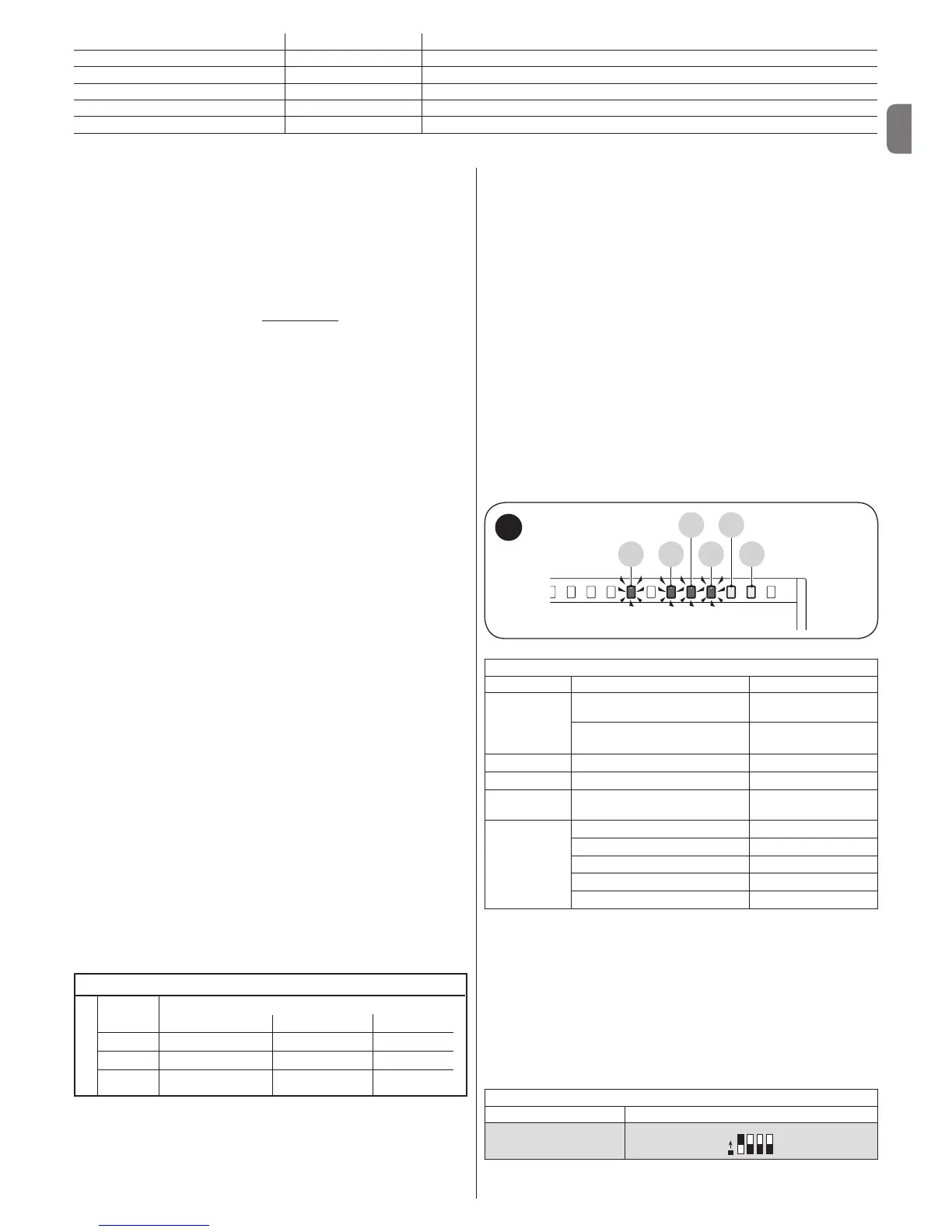
3. If the connections are correct, the LED for the “NC”-type inputs will be on,
while those for the “NO” type inputs must be off. See g. A and Table 2a.

 Loading...


