2 – English
Function Input type Description
PARTIAL OPEN TYPE 1 NO Fully opens the upper leaf
PARTIAL OPEN TYPE 2 NO Opens the two leaf half way
To check the parts of the control unit see g. 2.
Key to g. 2:
A 24 V AC power supply socket
B Back-up PS124 battery / Solemyo solar energy power supply
system socket (for further details see chapter 6.3)
C Services fuse (2A, type F)
D “SM” connection for radio receiver
E MotorterminalM1(partrstclosed)
F MotorterminalM2(partrstopened)
G Flashing lights output terminal
H OGI or electric locking output terminal
I 24 V DC terminals for services and phototest
L9..L13 Input LEDs
OK "LED OK" LED status
L1..L8 Programming LEDs
LR Radio programming LED
M Terminals for inputs
N Terminal for radio aerial
O Motor selector switch
Q Connector for IBT4N
R Networkfuse(see:technicalspecicationsofproduct)
S Networksupply(L-Line;N-Neutral)(see:technicalspecications
of product)
T Connection to earth
U Pressacavo
P1..P3 Buttons to programme control unit
P4 Button to programme radio
2.1 - Preliminary checks for installation
Before proceeding with installation, check the condition of the product compo-
nents, suitability of the selected model and conditions of the intended installa-
tion environment:
• Ensure that all conditions of use remain within the limits of product application
andwithinthe“Producttechnicalspecications”.
• Ensure that the selected installation environment is compatible with the over-
all dimensions of the product (g. 3).
• Ensure that the selected surfaces for product installation are solid and guar-
anteeastablexture.
•Makesurethatthexingzoneisnotsubjecttoooding.Ifnecessary,mount
the product raised from the ground.
• Ensure that the space around the product enables easy and safe completion
of manual manoeuvres.
• Make sure that the automation is provided with mechanical stops on both
closing and opening.
2.2 - Product application limits
The product may be used exclusively withWG2024, WG3524, WG4024,
WG5024,TOO3024,TOO4524,XME2024gearmotors.
2.3 - Installation
To install the control unit, proceed as shown in g. 4. Also observe the follow-
ing warnings:
• The control unit is supplied in an enclosure that if correctly installed assures
anIP54protectionrating.Thecontrolunitisthereforesuitableforinstallation
outdoors.
•Fixthecontrolunittoaat,vertical,non-removablesurfacethatisadequately
protected from potential impacts. Important! – The bottom of the control unit
must be at least 40 cm from the ground.
• Insert the dedicated cable clamps or pipe glands into the lower part of the
enclosure (g. 4). Important! – If the cable protection tubes end in a pit, it is
likely that condensation will form inside the control unit, which will damage the
electronic board. In this case, protect the control unit adequately so as to pre-
vent the formation of condensation.
• The cable clamps can be inserted on the long side of the enclosure only if the
control unit is installed in a protected indoor environment.
To install the other devices present in the automation, refer to the relevant
instruction manuals.
2.4 - Electrical connections
IMPORTANT!
– All electrical connections must be made with the unit disconnected
from the mains power supply and with the buffer battery disconnected,
if present in the automation.
– Connections must be made exclusively by qualied personnel.
– Make sure that all the electric cables used are of a suitable type.
01. Loosen the screws of the cover.
02. Prepare the electrical cable routing holes.
03. Connect the cables, referring to the electrical diagram shown in g. 5. To
connect the electrical power supply cable, vedere g. 2 e g. 6 nei punti
R, S, T, U. To secure the cable, use the cable clip U.
Note – To facilitate cable connections, the terminals can be removed from
their seats.
• With the exception of the photocell inputs when the PHOTOTEST function
is activated, if the inputs of the NC (Normally Closed) contacts are not in use
they should be jumped with the “COMMON” terminal. Refer to paragraph
2.4.3 for further information.
• If there is more than one NC contact on the same input, they must be con-
nected in SERIES.
• If the inputs of the NO (Normally Open) contacts are not used they should be
left free.
• If there is more than one NO contact on the same input, they must be con-
nected in PARALLEL.
• The contacts must be electromechanical and potential-free. Stage connec-
tions,suchasthosedenedas“PNP”,“NPN”,“OpenCollector”,etc.arenot
allowed.
• in the case of overlapping doors, you can select which motor must start
openingrstbyconnectingittoterminalM2.
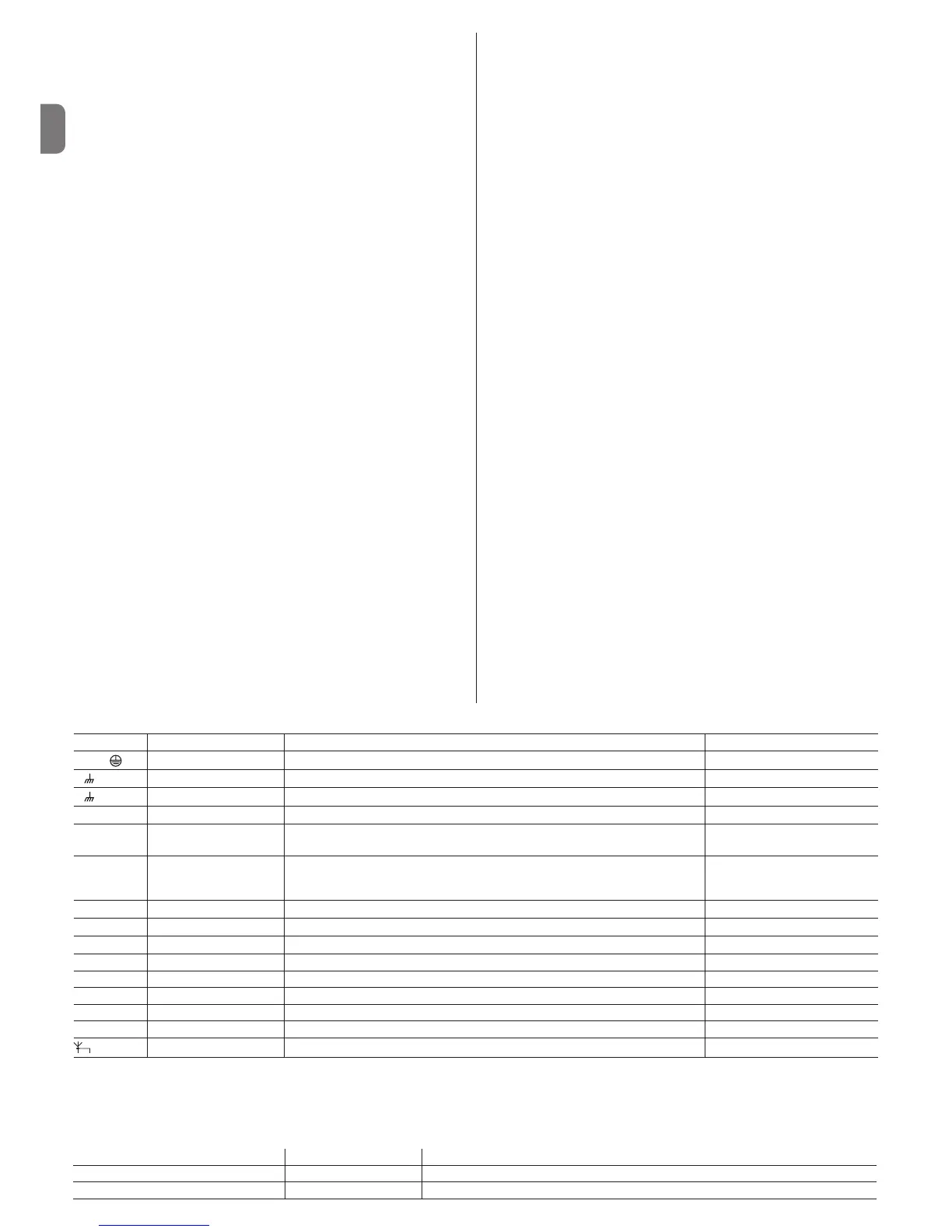
Key to gs. 2 - 5a - 5b - 5c:
Terminals Function Description Type of cable
L - N -
Power supply line Mains power supply 3x1,5mm
2
M M
Motor 1 M1 motor connection (Note 1) 3x1,5mm
2
M M
Motor 2 M2 motor connection 3x1,5mm
2
1÷2 Flashing light
Connectionofashinglight24V
𝌂
max25W
2 x 1 mm
2
3÷4 Open Gate indicator /
Elect.Lock
Connection for Open Gate Indicator 24 V
𝌂
max5WorElectriclock12V
𝌂
max
25VA(“Seechapter5-Programing”)
OGI:2x0,5mm
2
Electric lock: 2 x 1 mm
2
5
Common 24 V
𝌂
(with
Everything in stand by /
phototest)
Power Supply +24 V
𝌂
for TX photocells with phototest (max. 100 mA); “COM-
MON” for all inputs, safety, with “Everything in stand by” function activated (Note 2)
1x0,5mm
2
6
0 V
𝌂
Power supply 0V
𝌂
for services
1x0,5mm
2
7
24 V
𝌂
Power input for services, without “Everything in stand by” (24 V
𝌂
max 200 mA)
1x0,5mm
2
8
Common 24 V
𝌂
Common for all inputs (+24 V
𝌂
) without “Everything in stand by”
1x0,5mm
2
9 ALT Input with ALT function (emergency, safety shutdown) (Note 3) 1x0,5mm
2
10 PHOTO NC Input for safety devices (photocells, sensitive edges) 1x0,5mm
2
11 PHOTO 1 NC Input for safety devices (photocells, sensitive edges) 1x0,5mm
2
12 STEP BY STEP Input for cyclical functioning (OPEN-STOP-CLOSE-STOP) 1x0,5mm
2
13 AUX Auxiliary input (Note 4) 1x0,5mm
2
Aerial Connection for the radio receiver aerial screenedcabletypeRG58
Note 1 – This is not used for single leaf gates (the control unit automatically recognises if only one motor has been installed).
Note 2 – The “Everything in stand by” function serves to reduce consumptions. For further details on the electrical connections refer to paragraph 2.4.1 ““Every-
thing in stand by/Phototest connection” and for programming refer to chapter 5.2 “Programmable functions”.
Note 3 – The STOP input can be used for “NC” or constant resistance 8.2 kΩ contacts during auto-recognition (please refer to the “Programming” chapter).
Note 4 – The AUX factory auxiliary input is programmed with the “Partial open type 1” function but can be programmed with any of the following functions:

 Loading...


