GB
5
2.3.2) Description of connections
A brief description of the possible control unit output connections follows.
Terminals Function Description
1-2 : LUCY/TX Photo Auxiliary output (24Vac). The LUCY 24Vac flashing light (alternate current – maximum
lamp power 25W) and the photocell transmitter if the “Photo-test” function is
programmed can be connected to this output (see Figs. 6a-6b).
3-4 : 24Vac 24Vac output (alternate current) for powering services (Photocells, Radio, etc.)
max. 200mA.
5-6: Stop Input with “Stop” function (emergency, shutdown or extreme safety). It is normally closed.
5-7: Photo Input for safety devices (photocells, pneumatic edges). It is normally closed.
5-8: Step-by-step Input for cycle function control (Open - Stop - Close – Stop”), the “Step-by-step”
button (item G, Fig. 1a) activates this input.
9-10: Aerial Input for the optional radio receiver aerial.
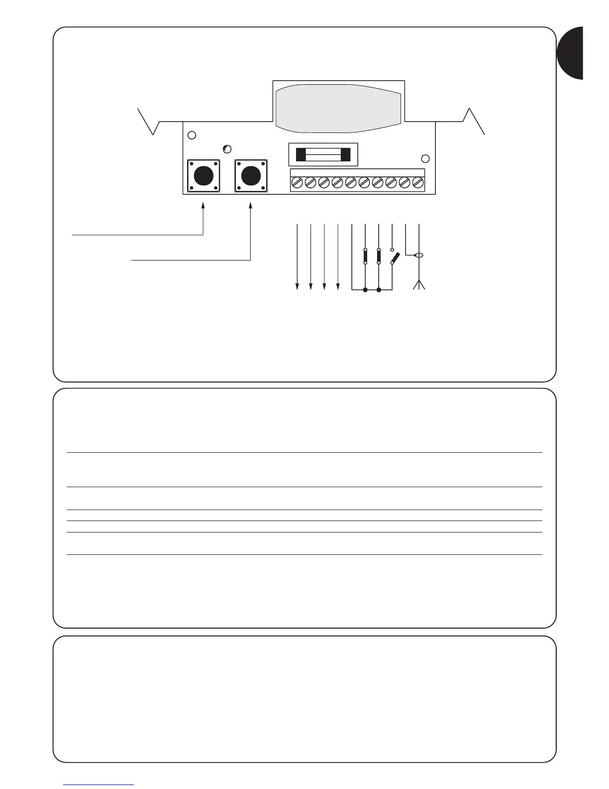
2.3.1) Electrical diagram
PROGRAMMING BUTTON (PROG)
“STEP-BY-STEP” BUTTON
LUCY / TX PHOTO
0V
0V
24 Vac
COMMON
STOP
PHOTO
STEP-BY-STEP
AERIAL
2.3.3) Notes about connections
Most connections are extremely simple; many of them are direct
connections to a single user point or contact.
The following figures show examples of how to connect external
devices.
Figs. 5: Connecting the flashing light and photocells with “Photo-
test” deactivated.
Figs. 6: Connecting the flashing light and photocells with “Photo-
test” activated.
Figs. 7: Connecting the key switch.
Figs. 8: Connecting the external radio.
(Please refer to the drawings on the cover)