21
Step 4
The center section is placed exactly in the middle of
the space set aside on the base.
All models larger than the VPM 600 are equipped
with lifting eyes. If chains or straps are used directly
on the brackets, the mutual angle must be greater
than 60 °. If this is impossible due to lack of space, a
lifting beam or similar must be used.
See the section “Transport after unpacking” for
proper handling.
NB. The VPM600 is delivered on a fi rm base.
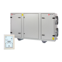
Step 5
The enclosed sealing tape is pasted on both end faces
by pulling off the protective paper.
If the unit is equipped with a discharge module, seal
seals must also be inserted between the discharge
module and the fi lter / fan sections.
a. Sealing tape
a
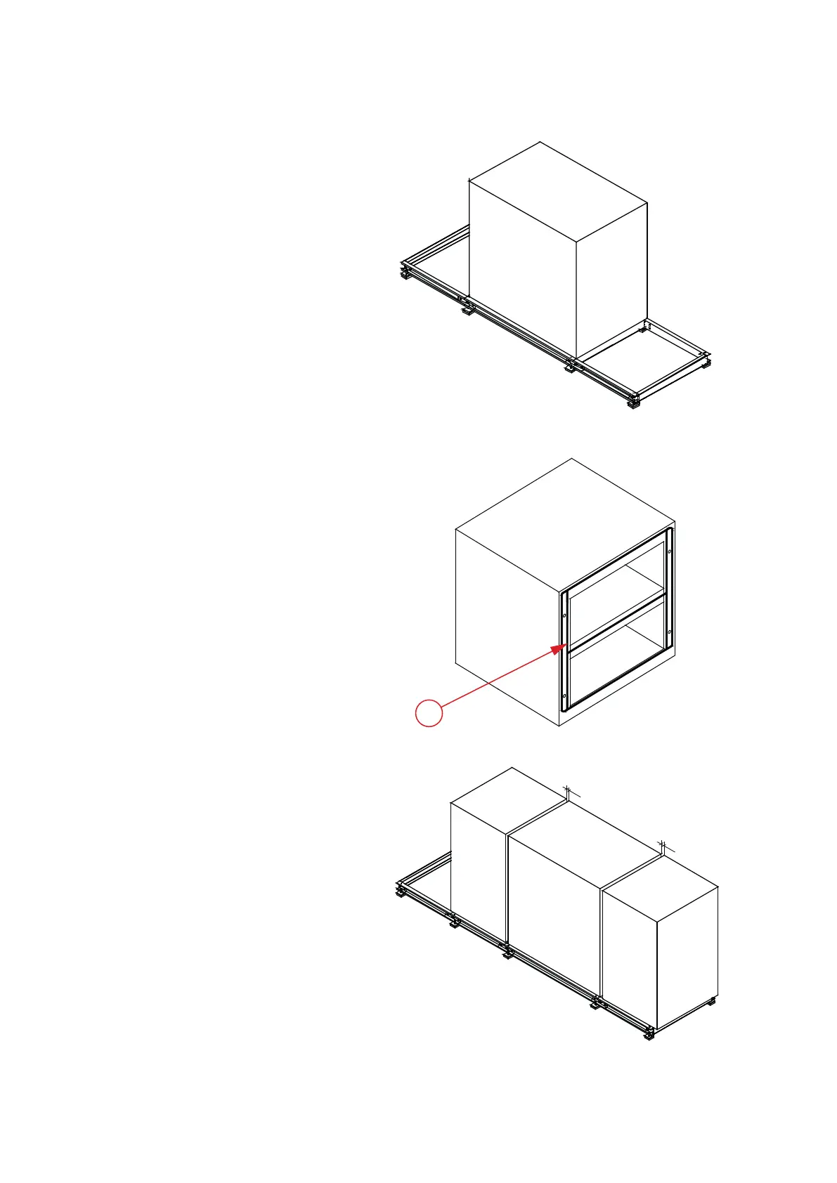
Step 6
The fi lter / fan sections are placed approx. 60 mm
from the center section.
60mm
60mm
Step 7
The fi lter / fan sections are pulled, with the help
of the enclosed brackets / bolts, together with the
center section.
The brackets are placed in the square grooves at the
bottom of the sections.
The bolts are tightened and the sections are pulled
together.
After installation, the square grooves are fi lled with
silicone.
a. Brackets
b. Bolt
Step 8
The modules are now screwed together with the
supplied steel set screws 10x130mm.
At each end of the sections there are 4 suitable
holes, 2 in each post, intended for this purpose.
For the VPM 3200, however, there are 6 holes at
each end.
 Loading...