22
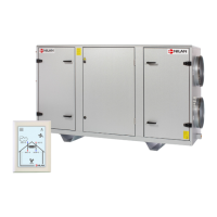
Step 7
The fi lter / fan sections are pulled, with the help
of the enclosed brackets / bolts, together with the
center section.
The brackets are placed in the square grooves at the
bottom of the sections.
The bolts are tightened and the sections are pulled
together.
After installation, the square grooves are fi lled with
silicone.
a. Brackets
b. Bolt
a
b
a
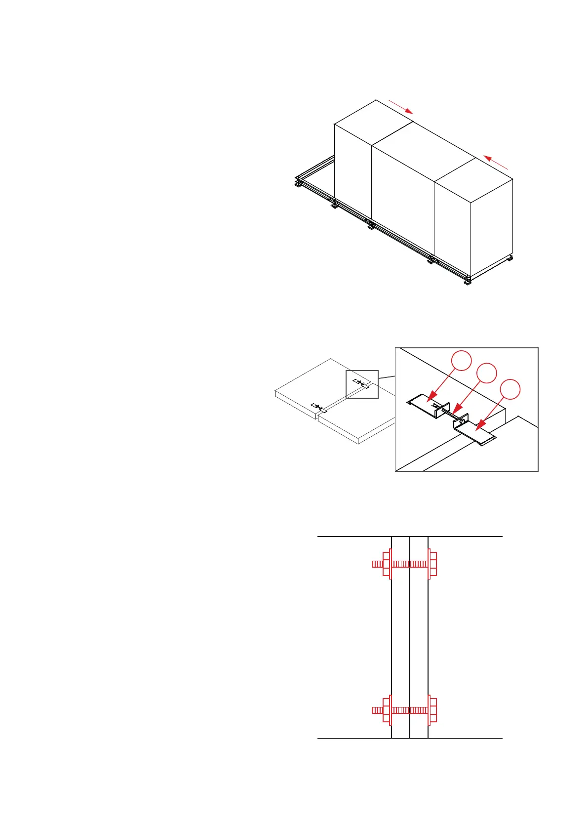
Step 8
The modules are now screwed together with the
supplied steel set screws 10x130mm.
At each end of the sections there are 4 suitable
holes, 2 in each post, intended for this purpose.
For the VPM 3200, however, there are 6 holes at
each end.
 Loading...