35
(800) BUY-HIFI NILES AUDIO CORPORATION
TM-AM/FM INSTALLATION INSTRUCTIONS
INSTALLATION
WARNING: Always turn the power OFF on the
Intellicontrol ICS Modular MultiZone Receiver and be
sure the AC line cord is disconnected to avoid damage
and electrical shock before making any connections to
the TM-AM/FM Module.
CAUTION: The TM-AM/FM Module is susceptible to static
discharge. Be sure to use a grounding strap or touch an
earth ground prior to picking up the TM-AM/FM. Handle
the card by its edges.
1. Carefully slide the TM-AM/FM Module into the
appropriate card slot. (Refer to the GXR2 Installa-
tion Worksheet to assure proper card slot number.)
2. Concentrate on the GXR2 card cage guides as you
insert the module
card.
3. Be sure the multi-pin
connector is secured
to the header in the
card cage.
4. Tighten thumbscrews.
(Do not over tighten)
CONNECTING AN ANTENNA TO THE TM-AM/FM
MODULE CARD
When all modules are in place, and the system compo-
nents have been installed, connect AM and FM antennas.
AM ANTENNA
1. Connect bare wire ends on antenna to dual spring
clips on TM-AM/FM (polarity not critical).
2. Position loop antenna for best reception.
FM ANTENNA
1. Connect F-type connector on antenna to F-type termi-
nal on TM-AM/FM.
2. Spread “arms” of dipole antenna as far apart as
possible and position for best reception.
Figure 2. TM-AM/FM Module connection to antennas.
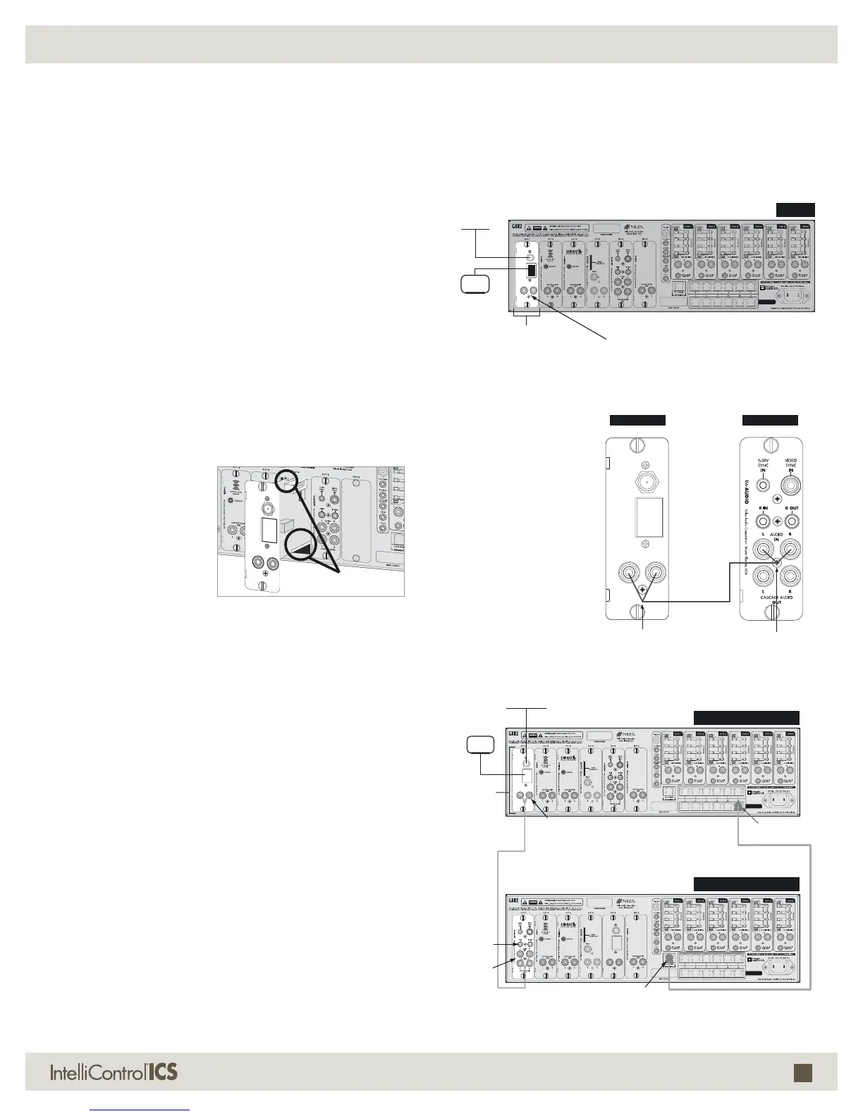
EXPANDING THE SYSTEM
When using multiple
chassis, connect the
Left and Right Cas-
cade Audio OUT of
the TM-AM/FM to
the Left and Right
Audio IN on the
IM-AUDIO Module
in the same num-
ber card slot on the
Slave chassis. Up
to four Slave chas-
sis may be used in
a system.
7*%&0
065
$"4$"%&"6%*0
065
'.
"/5
5.".'.
".
"/5
-
3
$"4$"%&"6%*0
065
/JMFT"VEJP$PSQPSBUJPO.JBNJ'MPSJEB64"
(93
5.".'.
.PEVMF
".-PPQ
"OUFOOB
$BTDBEF
"VEJP0VU
'.%JQPMF
"OUFOOB
$0..6/*$"5*0/
$0/530-48*5$)
-3$BTDBEF
"VEJP0VU
-3
"VEJP*O
4UFSFP3$"
UP3$"$BCMF
.BTUFS(93
5.".'..PEVMF *."6%*0.PEVMF
4MBWF(93
'.
"/5
5.".'.
".
"/5
-
3
$"4$"%&"6%*0
065
/JMFT"VEJP$PSQPSBUJPO.JBNJ'MPSJEB64"
7*%&0
065
$"4$"%&"6%*0
065
'.
"/5
5.".'.
".
"/5
-
3
$"4$"%&"6%*0
065
/JMFT"VEJP$PSQPSBUJPO.JBNJ'MPSJEB64"
7*%&0
065
$"4$"%&"6%*0
065
'.
"/5
5.".'.
".
"/5
-
3
$"4$"%&"6%*0
065
/JMFT"VEJP$PSQPSBUJPO.JBNJ'MPSJEB64"
(93.BTUFS$IBTTJT
(934MBWF$IBTTJT
5.".'.
.PEVMF
*."6%*0
.PEVMF
4UFSFP
3$"3$"
$BCMF
&YQBOTJPO
065UPNBTUFS
".-PPQ
"OUFOOB
$BTDBEF
"VEJP0VU
$PNNVOJDBUJPO
BOE$POUSPM4XJUDI
$BU$BCMF
'.%JQPMF
"OUFOOB
"VEJP*O
$0..6/*$"5*0/
$0/530-48*5$)
$0..6/*$"5*0/
$0/530-48*5$)
Figure 3. Cascade Audio Connections.
Figure 4. Expanded System with Cascade Audio Connections.
EXAMPLES OF INTELLICONTROL
®
ICS SYSTEM CONFIGURATIONS
L&R
Audio In
L&R Cascade
Audio Out
Stereo
RCA to
RCA
Cable
Figure 1. Inserting the module card
into the GXR2 card cage.
'.
"/5
5.".'.
".
"/5
-
3
$"4$"%&"6%
*0
065
/JMFT"VEJP$PSQPSBUJPO.JBNJ'MPSJEB64"
Guides

 Loading...