45
(800) BUY-HIFI NILES AUDIO CORPORATION
USER INTERFACES
CAT-5 CONNECTION
WIRING TERMINATION DIAGRAM
The IntelliControl ICS touch screens and keypads con-
nect to the IntelliControl ICS Modular MultiZone Receiver
via CAT-5 cable. For the system to function properly all
runs of CAT-5 must be pulled in home-runs from the
touch screen locations to the system head end where
the IntelliControl ICS Modular MultiZone Receiver and
other system components will be located.
The runs of CAT-5 must be terminated with RJ-45 connec-
tors using the T-568A pinout confi guration as follows:
Pin # Description Color Code
1 TX+ White/Green
2 TX– Green
3 RX+ White/Orange
4 IR Signal Blue
5 IR Ground White/Blue
6 RX– Orange
7 UI Power White/Brown
8 UI Ground Brown
Note: TX+ = transmit, RX+ = receive, UI = user interface.
1JO
5"
H ( P # C 0 CS #3
5"
H ( P # C 0 CS #3
RJ-45 Plugs
GXR2
4ZTUFN *34FOTPS 4ZTUFN *34FOTPS
CAT-5 Cable
System
Terminal
SINGLESINGLE
$-"444&-7%&7*$&
%*41-":,&:1"%
ª/JMFT"VEJP$PSQPSBUJPO
.JBNJ'MPSJEB64"-""$/
5IJTEFWJDFDPNQMJFTXJUIQBSUPGUIF'$$3VMFT
0QFSBUJPOJTTVCKFDUUPUIFGPMMPXJOHUXPDPOEJUJPOT
5IJTEFWJDFNVTUBDDFQUBOZJOUFSGFSFODFBOEUIJT
EFWJDFNVTUBDDFQUBOZJOUFSGFSFODFSFDFJWFEJODMVEJOH
JOUFSGFSFODFUIBUNBZDBVTFVOEFTJSFEPQFSBUJPO
4:45&. *34&/403
$0..6/*$"5*0/
$0/530-48*5$)
$"5$BCMF$"5$BCMF
4ZTUFN
5FSNJOBM
DISPLAYDISPLAY
GXR2
$-"444&-7%&7*$&
ª/JMFT"VEJP$PSQPSBUJPO
.JBNJ'MPSJEB64"-""$/
$0/5"$5,&:1"%
5IJTEFWJDFDPNQMJFTXJUIQBSUPGUIF'$$3VMFT
0QFSBUJPOJTTVCKFDUUPUIFGPMMPXJOHUXPDPOEJUJPOT
5IJTEFWJDFNVTUBDDFQUBOZJOUFSGFSFODFBOEUIJT
EFWJDFNVTUBDDFQUBOZJOUFSGFSFODFSFDFJWFEJODMVEJOH
JOUFSGFSFODFUIBUNBZDBVTFVOEFTJSFEPQFSBUJPO
4:45&. *34&/403
$"5$BCMF
4ZTUFN
5FSNJOBM
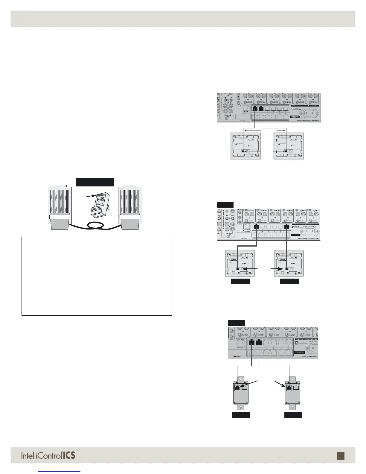
Contact connecting to the
Communication and Control Switch
Display Keypad connecting to the
Communication and Control Switch
Single Keypad connecting to the
Communication and Control Switch
Important: All CAT-5 runs must be terminated
using T-568A pinouts.
EXAMPLES OF INTELLICONTROL
®
ICS SYSTEM CONFIGURATIONS
CONNECTIONS
Using a properly configured CAT-5 cable, connect
the system terminal on the touch screen to any of the
RJ-45 communication and control hub ports on the
IntelliControl ICS Modular MultiZone Receiver as shown
in the following diagrams.

 Loading...