ELECTRICAL SYSTEM
SERVICE MANUAL
ENGLISH
SC350 9098840000
21
ELECTRICAL SYSTEM
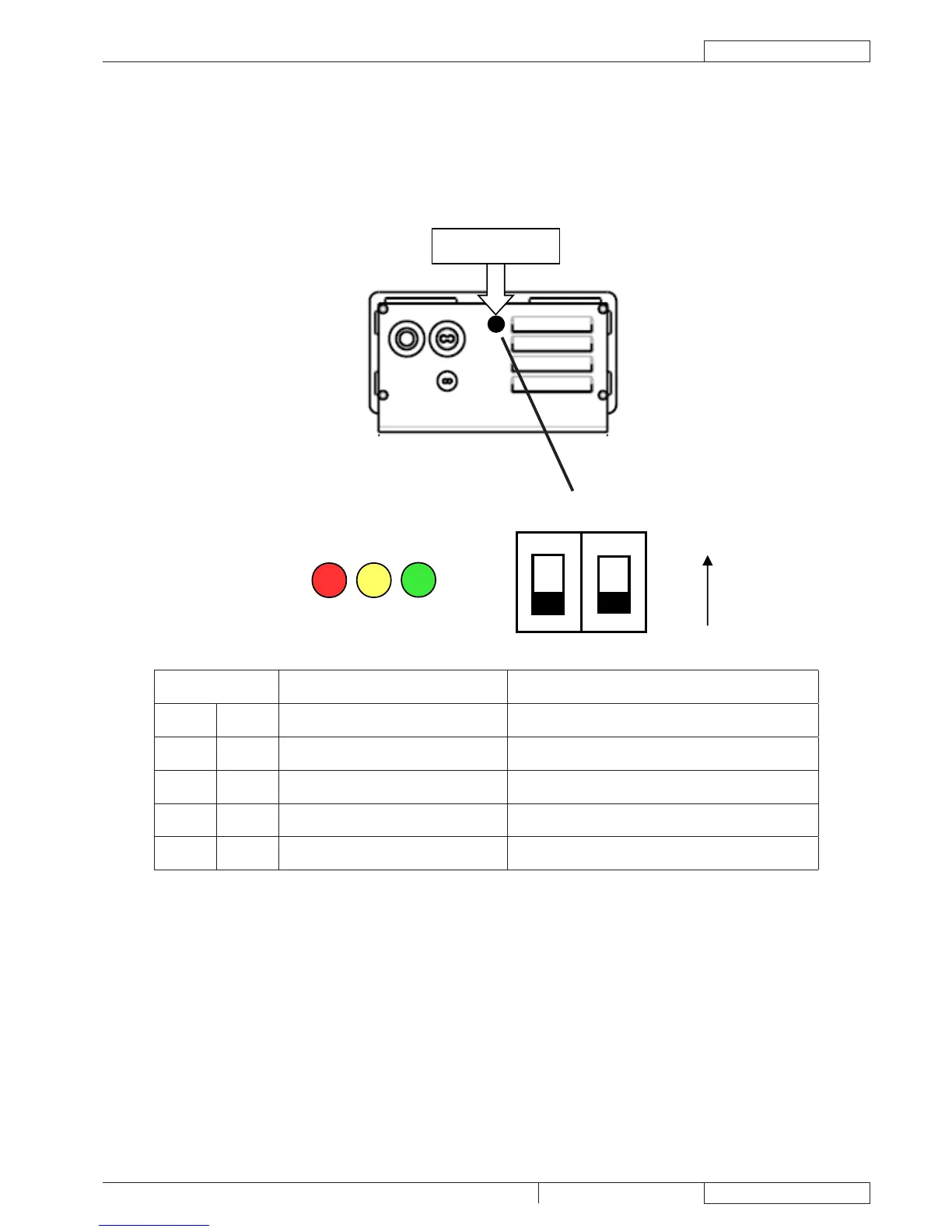
BATTERY CHARGER SETTING DIPSWITCH CONFIGURATION
To change the dipswitch conguration, please remove the round black cap located close to the openings on the bottom of the
charger (see the picture below), using a tool like a screwdriver.
SW1 LED CODE (*) CHARGING CURVE
DP1 DP2 Battery LEDs
ON ON 2 ashes of GREEN IUU0-GEL for generic Gel and AGM batteries
ON OFF 2 ashes of RED & GREEN IUIa-AGM for DISCOVER AGM batteries
OFF ON 2 ashes of YELLOW & GREEN IUIa-OPTIMA for OPTIMA batteries (default)
OFF OFF 2 ashes of YELLOW IUIa-GEL for EXIDE SONNENSCHEIN Gel batteries
The LED code is shown by the battery status LEDs every time the charger is powered on, before to start the charging cycle.(*)
BATTERY CHARGER ADDITIONAL FUNCTIONS
The battery charger is also used for:
Check the battery voltage during machine operation.1.
Display the battery status through the LED (EB1).2.
Stop the machine when the battery is discharged.3.
Avoid the machine operation during the battery recharging.4.
For this porpouse the following auxiliary battery charger contacts are used:
B1: (ref. + 12V) input signal for switching on the machine. –
B2: (refer to 0V) output signal for activating machine functions. –
 Loading...