Electrical System 22Service Manual – SC351
Electrical System
Functional Description
The program selection knob/rotary switch (SW1) and the machine start-up enabling push-button (SW2) con-
trols the vacuum brush motor relay (K1) for the activation of the brush motor (M1) and the vacuum system
motor relay (K2) for the activation of the vacuum system motor (M2).
The solenoid valve (EV) is controlled by the solenoid valve timer relay (KT1) when the solution ow switch
(SW3) is turned to 0 (minimum ow); the timer is bypassed when the solution ow switch (SW3) is turned to
1 (maximum ow).
The battery charger (CH) supplies negative power to all the control relays only when the battery charge is suf-
cient and the battery charger is not connected to the electrical mains.
The machine system is connected to the battery with the connector (C1).
Fuses
The brush motor (M1) is protected by the brush motor fuse (F1). The vacuum system motor (M2) is protected
by the vacuum system motor fuse (F2). The solenoid valve (EV) is protected by the function selector fuse (F3).
The battery charger (CH) has inner safety protections which are not accessible.
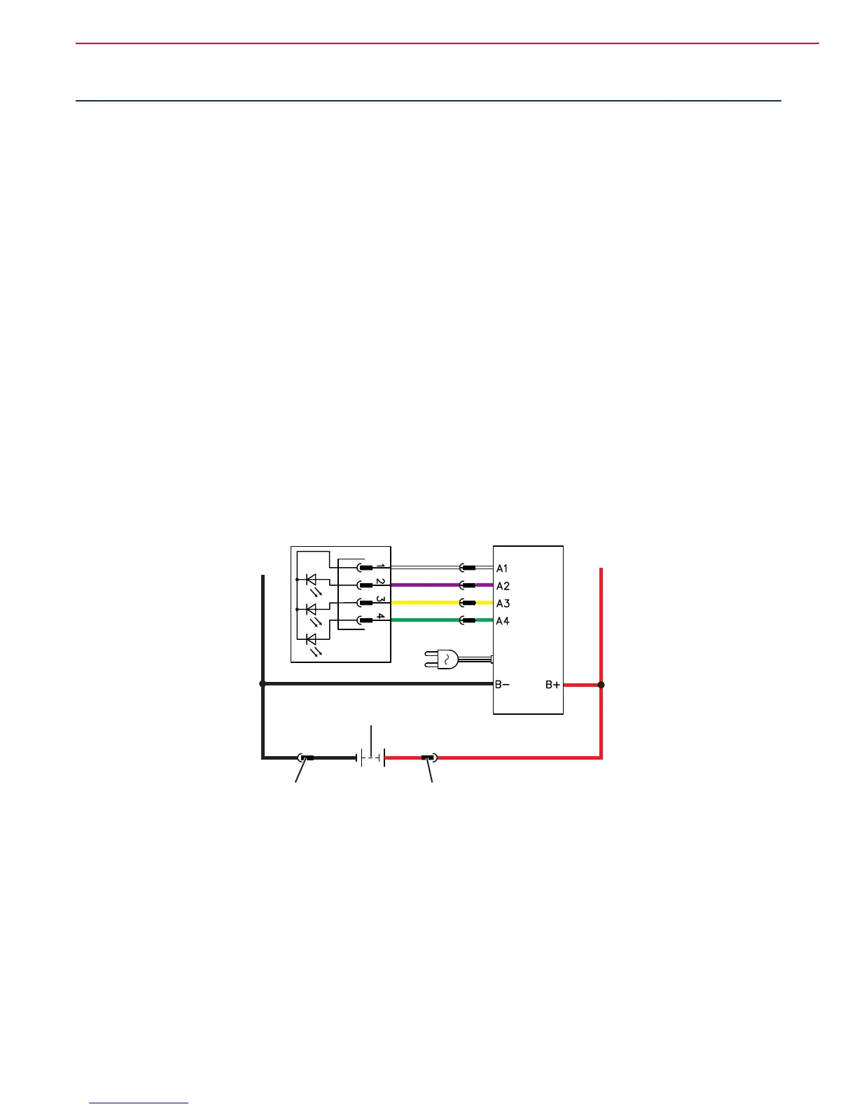
Wiring Diagram
12 V BATTERY (BAT)
CONNECTOR (C1)
BATTERY CHARGER (CH)
ELECTRONIC BOARD (EB1)
CONNECTOR (C1)
RYG
P100781

 Loading...


