Recovery System 30Service Manual – SC351
Recovery System
Functional Description
The water recovery system removes the dirty water from the oor and pipes it to a recovery tank. When the
machine is running, the dirty water on the oor is collected by the squeegee blades and collected through the
slots in the same, piped through the vacuum hose and into the tank by the airow created by vacuum motor
(M2). The dirty water is piped into the recovery tank, while the airow continues to the vacuum fan.
The vacuum system motor (M2) is supplied by the vacuum system motor relay (K2) which is driven by the
program selection knob/rotary switch (SW1) when it is turned to 1 or 3. The circuit is protected by the vacuum
system motor fuse (F2).
The automatic oat in the vacuum grid stops vacuum system motor (M2) from collecting any liquids.
When the automatic oat closes and shuts down the vacuum system, the vacuum system motor noise will in-
crease and the oor will not be dried.
When the recovery tank is full it must be emptied.
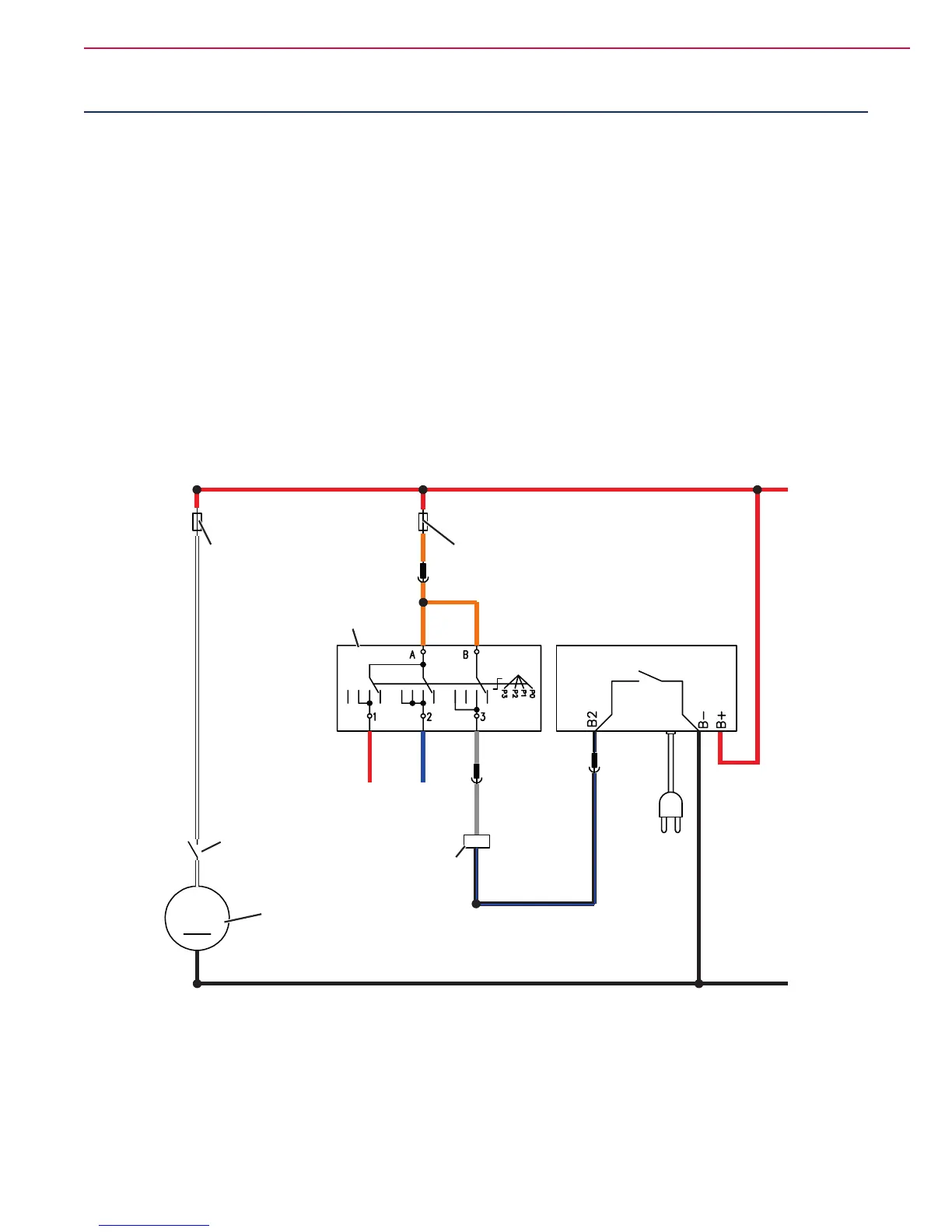
Wiring Diagram
BATTERY CHARGER (CH)
VACUUM SYSTEM
MOTOR FUSE (F2)
FUNCTION
SELECTOR FUSE (F3)
VACUUM SYSTEM
MOTOR RELAY (K2)
VACUUM SYSTEM
MOTOR RELAY (K2)
VACUUM SYSTEM
MOTOR (M2)
PROGRAM SELECTION
KNOB/ROTARY SWITCH (SW1)
P100786

 Loading...


