Electrical System 25Service Manual – SC351
Battery Charger Setting and Dipswitch Conguration
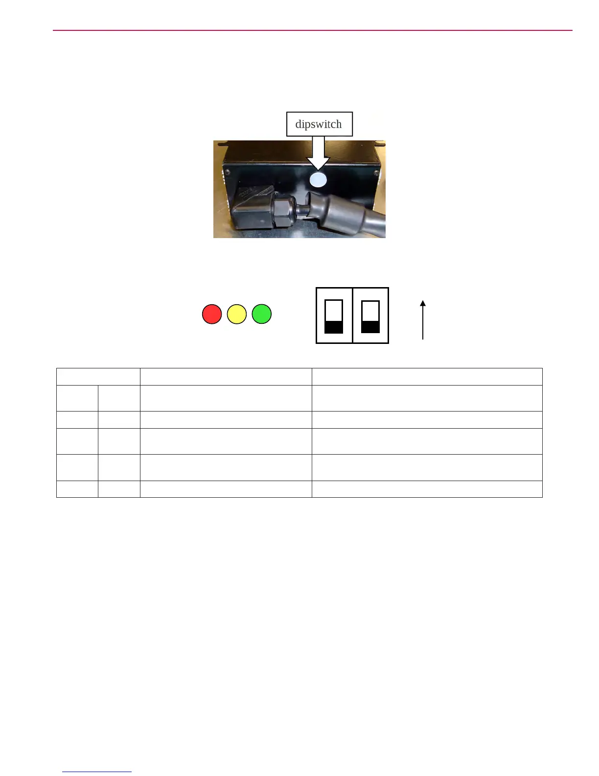
To change the dipswitch conguration, remove the round white cap near the openings (see the illustration
below), with a screwdriver.
P100782
CBHD2 12V 12A IUIa OPTIMA DIPSWITCH CONFIGURATION
SW1 LED CODE(*) CHARGING CURVE
DP1 DP2 Battery LEDs
ON ON 2 flashes of GREEN IUU0-GEL for generic Gel and AGM batteries
ON OFF
2 flashes of
RED&GREEN
IUIa-AGM for DISCOVER AGM batteries
OFF ON
2 flashes of
YELLOW&GREEN
IUIa-OPTIMA for OPTIMA batteries
(default)
OFF OFF 2 flashes of YELLOW
IUIa-GEL for EXIDE SONNENSCHEIN Gel
batteries
(*) the LED code is shown by the battery status LEDs every time the charger is powered on,
before to start the charging cycle.
To change the dipswitch configuration, please remove the round black
cap located close to the openings on the bottom of the charger (see the
picture below), using a tool like a screwdriver.
dipswitch
ON
OFF
OFF
ON
ON
SW1
DP1 DP2
RED YELLOW GREEN
LED LED LED
P100783
SW1 LED CODES (*) CHARGING CURVES
DP1 DP2 BATTERY CHARGING LEDS (on the control
panel)
ON ON 2 ashes of the GREEN LED Charging algorithm for generic Gel and AGM battery
ON OFF 2 ashes of the RED and GREEN LEDS Charging algorithm for AGM DISCOVER battery
(default for Advance model)
OFF ON 2 ashes of the YELLOW and GREEN LEDS Charging algorithm for OPTIMA battery
(default for Nilsk model)
OFF OFF 2 ashes of the YELLOW LED Charging algorithm for EXIDE SONNENSCHEIN Gel battery
(*) The LED codes are shown by the battery charge indicators each time that the battery charger is turned
on, before the charging cycle starts.
Battery Charger Auxiliary Functions
The battery charger is also used to:
7. Check the battery voltage during machine operation.
8. Display the battery charge level with the led electronic board (EB1).
9. Stop the machine operation when the battery is discharged (10.8 V).
10. Disable the machine operation during battery recharging.
For this reason, the following battery charger auxiliary contacts are used:
• B1: (ref. + 12 V) Enabling input for machine start-up.
• B2: (ref. 0 V) Output for machine function activation.

 Loading...


