106Service Manual – SC401, SCRUBTEC 344
24 - Electrical System (Battery)
Functional Description
The machine electrical system is mainly composed of
the following components:
• Battery: lead battery pack with 24V nominal
voltage. They are connected to the machine
system through the Battery red connector (C1),
which has the following functions:
– Permanently disconnecting the batteries in
case of extended interruption of use
– Outer battery charger connection
– Emergency stop of all the machine functions
(except for charging with the machine battery
charger, if present)
• Ignition key (K1) (if present): inhibits the use of
all the machine functions (except for charging
with the machine battery charger, if present), if
turned to 0 or with the key removed.
• Main machine controller (EB1): receives the
commands from the User interface controller
(EB2) and powers directly all the machine
services, except for the electric drive system (if
present).
• User interface controller (EB2): it is responsible
for the user interface, as it contains all control
buttons and the indicator LEDs, and is connected
to the two Operator presence sensors (S1, S2)
on the handlebars. All information from and for
the user is exchanged with the Machine Main
Controller (EB1) via I2C protocol.
• Main power relay (ES1): controlled by the Main
machine controller (EB1), it powers the electronic
board power circuits only after all system safety
and integrity conditions have been veried and
conrmed when the board is turned on.
• Wheel drive controller (EB3) (if present): it
powers the Drive motor (M4).
• Guards: the system is protected against short-
circuits and overloads by the following fuses:
– (F1, 30 Amp): Brush motor circuit fuse
– (F2, 30 Amp): Vacuum motor circuit fuse
– (F3, 30 Amp): Electric drive system fuse (if
present)
– (F4, 1 Amp): USB socket circuit fuse (if
present)
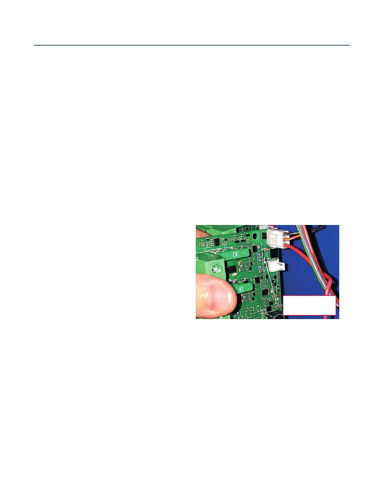
The low-power circuits not protected by those fuses
are protected by the electronic piloting components
or by self-resetting fuse (PTC) on the Main machine
controller (EB1).
Self-resetting fuse
(PTC)
• Machine battery charger (CH) (if present): to
recharge the batteries. When it is running, all
machine functions are inhibited.
 Loading...


