64Service Manual – SC401, SCRUBTEC 344 05 - Control System - Cord
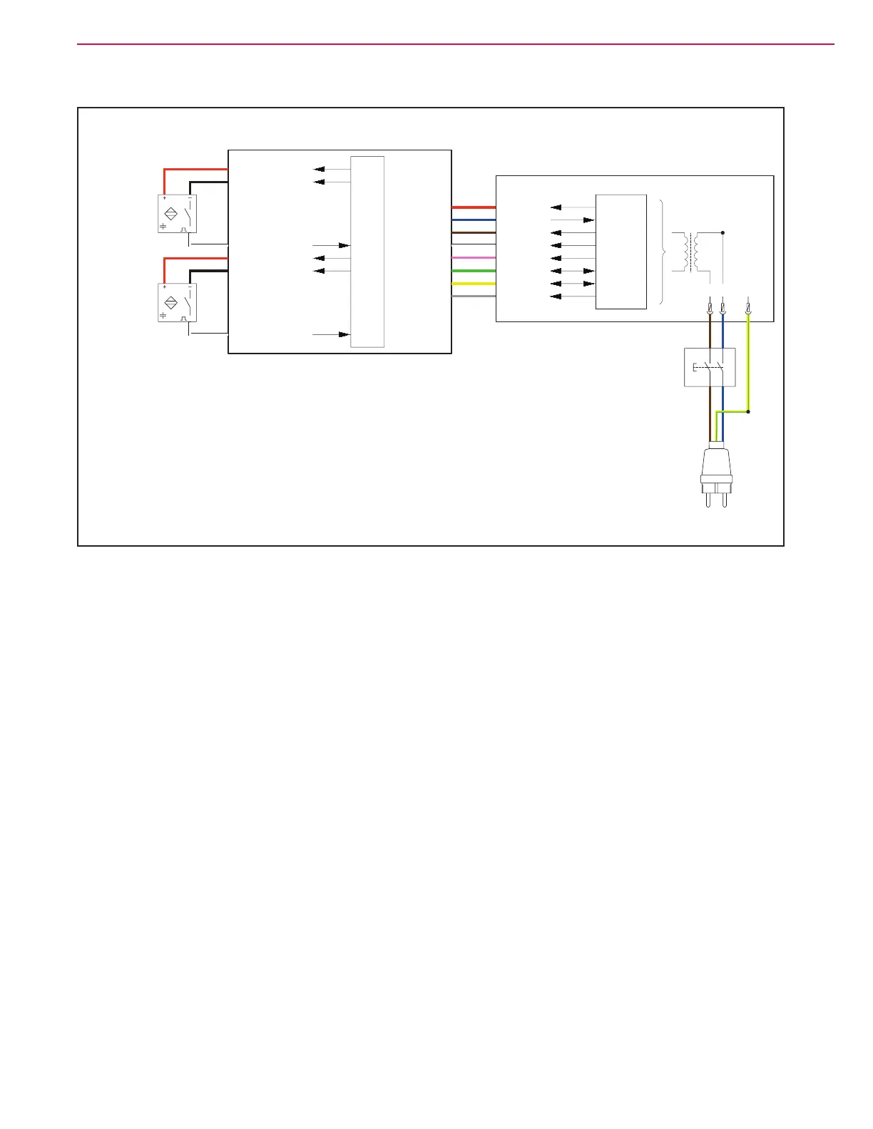
Wiring Diagram
A.2
MAIN MACHINE
CONTROLLER (EB1)
USER INTERFACE
CONTROLLER (EB2)
RH OPERATOR’S
PRESENCE SENSOR (S1)
LH OPERATOR’S
PRESENCE SENSOR (S2)
MAIN SWITCH
(SW1)
POWER PLUG
RIGHT.2
RIGHT.1
LEFT.2
LEFT.1
RIGHT.3
LEFT.3
5V
0V
5V
0V
ENABLE
ENABLE
A.1J201.8
J201.7
J201.6
J201.5
J201.4
J201.3
J201.2
J201.1
EXT.1
EXT.2
EXT.11
EXT.3
EXT.4
EXT.6
L
41
52
NPE
5V
IGNITION
5V
0V
SPI CS3
SPI MISO
SPI MOSI
SPI CLOCK
uP
uP
Left op. pres. sensor supply +
Left op. pres. sensor supply -
Left op. pres. sensor input
Right op. pres. sensor supply +
Right op. pres. sensor supply -
Right op. pres. sensor input
Power button output
Power button input
Power supply +
Power supply -
SPI CS3
SPI MISO
SPI MOSI
SPI clock
Power button output
Power button input
Power supply +
Power supply -
SPI CS3
SPI MISO
SPI MOSI
SPI clock
Figure 1:
 Loading...


