112Service Manual – SC401, SCRUBTEC 344 24 - Electrical System (Battery)
Battery Charger Setting and Dipswitches Conguration (continues)
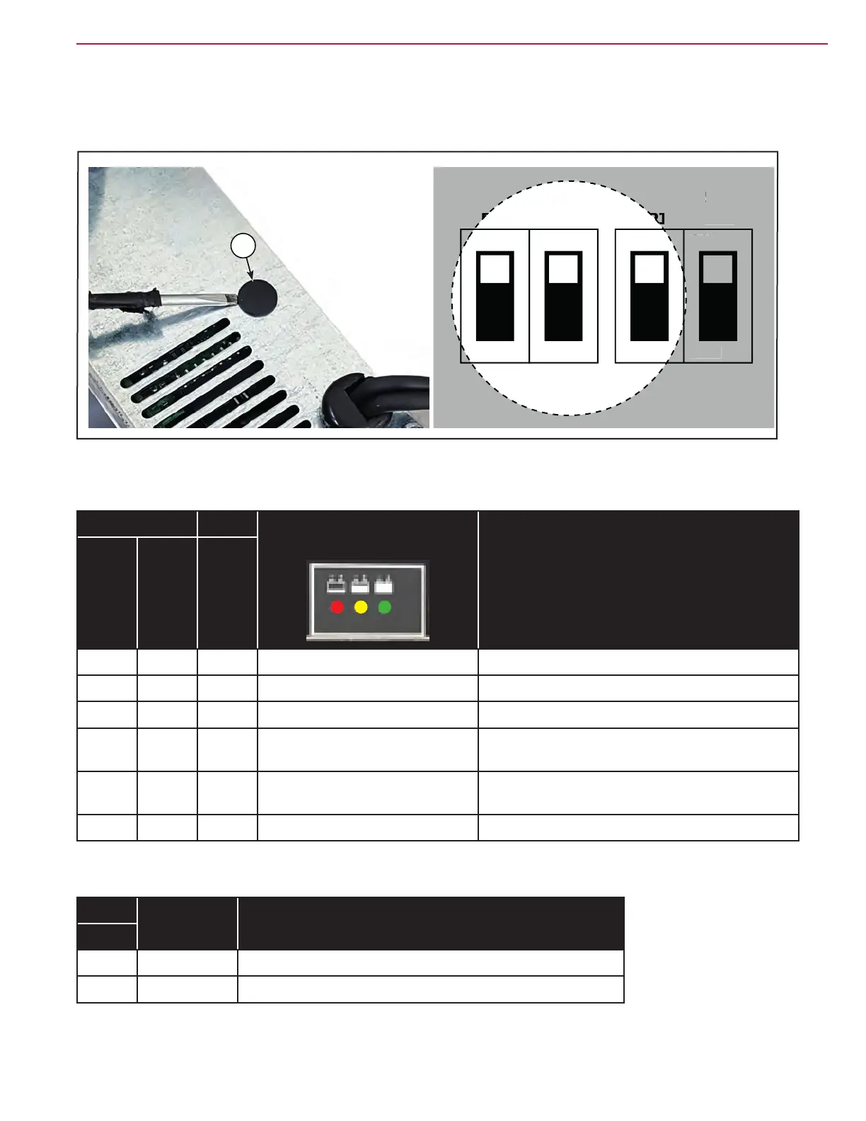
5. Remove the round black cap (E) located close to the openings on the bottom of the charger, using a tool
like a screwdriver.
Figure 6:
ON
DP1
SW1
OFF
ON
DP2
OFF
ON
DP1
SW2
OFF
ON
DP2
OFF
W
N
DP
F
E
6. Change the dipswitch conguration as the tabel below:
SW1 SW2 BATTERY CHARGER
LEDs CODE (*)
CHARGING CURVE
DP1 DP2 DP1
ON ON ON 2 ashes of RED Acd for Lead-acid (Wet) batteries
ON ON OFF 2 ashes of GREEN Gel for generic Gel and AGM batteries
ON OFF ON 2 ashes of RED and GREEN AGM for DISCOVER AGM batteries
ON OFF OFF 2 ashes of YELLOW and
GREEN
OPTIMA for OPTIMA batteries
OFF ON ON 2 ashes of YELLOW Gel for EXIDE SONNENNSCHEIN Gel batteries
(DEFAULT)
OFF ON OFF 2 ashes of RED and YELLOW AGM for FULLRIVER AGM batteries
(*) The LED CODE is shown by the battery charger status LEDs every time the charger is powered on, before
to start the charging cycle.
SW2 CHARGING
CURRENT
COMMENTS
DP2
ON 10A DEFAULT
OFF 8A To be used for batteries smaller than 50 Ah
7. Assemble the components in the reverse order of disassembly.
8. Connect the charger plug to mains to check the proper LED CODE.
 Loading...


