30Service Manual – SC6000 04 - Control System
Horn (Out): This is the output to the horn.
Float Switch (Recovery): This is the oat switch in the recovery
tank that closes when the tank is full.
Side Sweep (sensor): This is the input from the proximity sensor
for the optional side broom. When the side broom is in the up-
position, the sensor is active.
Solution Level Sensors 1, 2, 3, 4: These are the 4 inputs from the solution tank level sensors. The sensors
are normally closed, so they open as the solution level rises.
Horn Switch (In): This is the input from the horn switch on the
operator’s steering column.
BOP Switch: This is the input from the Burst of Power switch on
the operator’s steering column.
Solution Switch: This is the input from the solution switch on the
operator’s steering column.
Accelerometer X, Y, Z: These 3 inputs are from the machine’s accelerometers for X, Y, and Z directions.
These are used to sense machine movement and also register machine impacts. The units are 1/1000 G-force.
E3 Power Module
The Power Module menu provides information regarding all of the motors which are driven by the power
module. The list of information for each motor is as follows:
• Requested PWM %: This is the value (by percent) that the power
module has been instructed to apply to the particular motor.
• Output PWM %: This is the actual output PWM value (in
percent) that the power module is sending to the motor. When a
motor is rst started, its PWM out will be less than the requested
PWM, as the motor speed is gradually increased.
• Output Amps: This is the actual amperage the power module is recording for the particular motor.
The motors are referenced by number. The actual motors are listed below:
M1 = Right Brush
M2 = Left Brush
M3 = Side Sweep
M4 = Vacuum 1
M5 = Vacuum 2
M6 = Squeegee Lift Actuator
M7 = Deck Lift Actuator
M10 = Option Pump
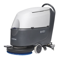
E2 Main Controller
J1-22 HORN
Back
Scroll
J2-8 FLOAT SW
J2-9 SIDE SWEEP
J2-10 LEVEL 1
0
0
1
1
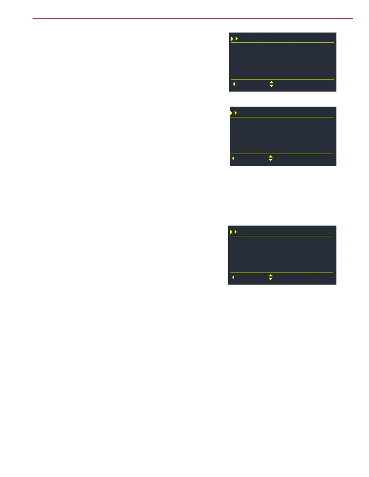
E2 Main Controller
J2-16 HORN SW
Back
Scroll
J2-17 BOP SW
J2-18 SOLUTION SW
ACCEL-X (mG)
0
0
0
-762
E3 Power Module
M1 PWM Req %
Back
Scroll
M1 PWM Out %
M1 Amps
M2 PWM Req %
0
0
0.0
0
 Loading...