78Service Manual – SC6000 24 - Electrical System
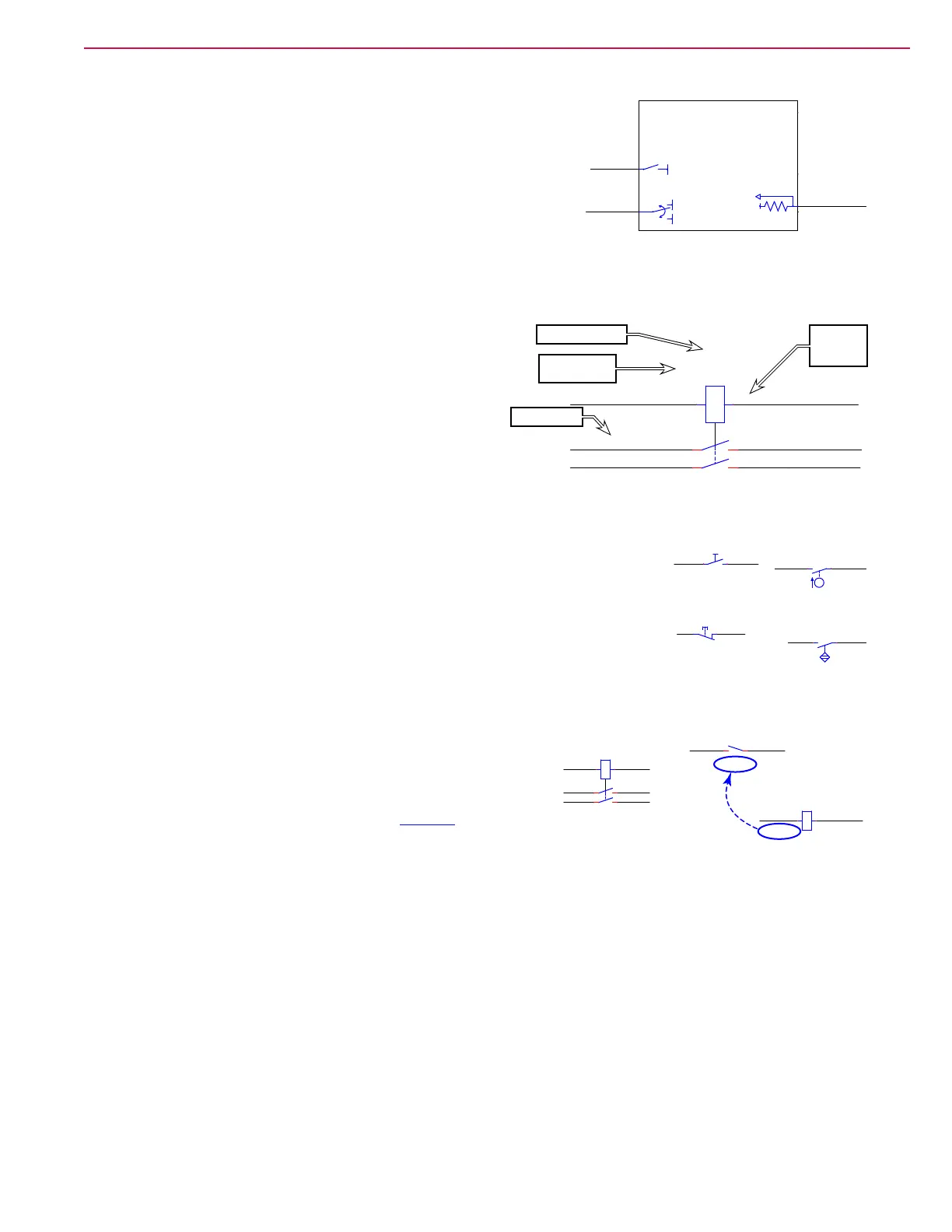
Common Schematic Symbols
Control Board Inputs and Outputs: Not all control board inputs
or outputs are given special symbolic meaning, but to the left are
a couple of commons symbols. The right-hand side shows an input
with a pull-up resistor. The signicance of this input is that when
the input is an open circuit, the pull-up resistor forces the input
positive. This type of input is active when the external device pulls
the signal to ground.
The two outputs on the left signify a PWM controlled output, with the upper symbol signifying a positive
PWM, and the lower symbol signifying a reversing positive/negative PWM control.
Identication:Each component on the schematic
contains a variety of identifying information that is useful
for troubleshooting and tracing circuits. The component
ID is used throughout the system to identify the device,
including in the controller menu display. The component
name helps identify the device as it relates to the machine
itself. The wire color identiers help for tracing wire
connections to the device, and when applicable, the
terminal numbers identify where those wires connect to the device.
Switches: Switches come in several types, but the most signicant aspect
about a switch is whether its contacts are normally-open or normally-closed.
Schematically, normally-open switches are drawn with the switch blade above
the contact position, and normally-closed switches are drawn with the switch
blade below the contact. Some switches are shown with additional pictographic
elements to signify the type of action used to control the switch. For example, a
oat switch uses a symbol resembling a oat ball.
Relays: Relays are solenoid-controlled switches. Whenever
possible, they are drawn with the relay coil and switch(s) stacked
vertically, with a dotted line between them to signify the control.
When the coil and contacts can’t be kept together, they use
similar reference tags to those described on page 77.
E2
MAIN CONTROL BOARD
J2-18
J1-9
J1-19
B-
+5V
B-
B+
YEL/BRN
ORN/BRN
YEL/BRN
YEL/BRN
BLU/RED
GRA
K1
1
0
KSI RELAY
8
4
6
2
Component ID
Terminal
Number
Component
Name
Wire Color
S8
SIDE SWEEP
1 2
S6
SWITCH, FLOAT
1
2
S2
SW EMERGENCY
S1
SW , SEAT
12
TO 2C5
K2
POWER MODULE
2
1
TO 2B2
K2
COIL, POWER MODULE
3 4
K1
1
0
KSI RELAY
8
4
6
2
 Loading...