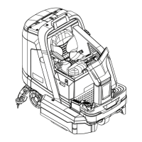
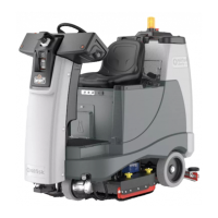
48Service Manual – SC6000
20 - Wheel System, Traction
Functional Description
The drive system of the SC6000 machine
consists of a single drive wheel with an
integral motor. The drive wheel connects
to the subframe with a rotational bearing
and ange to provide steering rotation.
Steering control is made through the
steering column that passes through a
universal joint to translate the rotation
from the angled steering wheel to the
vertical shaft and pinion sprocket. The
pinion sprocket drives a chain that wraps
around the steering sprocket. The steering
sprocket has no chain teeth, but the chain
is xed to the sprocket at the ends of the
chain using standard master links.
Drive Motor
The drive motor is a 3-phase, remotely commutated, AC induction motor; which is commonly referred to as
a brushless DC motor. Even though it is an AC motor, it is powered from a controlled DC power source that
simulates AC power. Each of the 3 motor windings is sequentially energized with either zero-volts, positive
battery voltage, or inverted battery voltage. This creates a rotating magnetic eld in the windings just like a
normal 3-phase AC motor.
Unlike a normal AC motor that just receives blind AC power at a given frequency, the drive motor functions
as a servo-motor, in that the motor provides positional feedback back to the motor driver for the actual
rotor position. This is referred to as remotely commutated. Two encoders inside the motor report the
actual rotational position of the rotor back to the controller. This permits the driver to know which of the 3
windings needs to be energized to rotate the motor in the desired direction, and even position. This type of
motor can literally be rotated a fraction of a turn and stopped, if desired.
The motor also reports its operational temperature back to the motor driver. This is a protection feature to
prevent motor damage due to excessive heat. The drive controller can either reduce power to the motor, or if
severe enough, shut down the motor.
Drive Pedal Potentiometer
The drive pedal potentiometer (R1 pot) is a variable resistor connected to the Pin J4-16 input of the drive
controller, with pins J4-15 and J4-18 as reference voltages. As the resistance changes, the drive controller
increases or decreases drive motor speed.
The drive pedal is set up in what’s called a wig-wag conguration, where drive direction is controlled by
a single potentiometer. When the throttle potentiometer is in the center position, the wiper voltage is
approximately 2.8 volts. The speed controller interprets any voltage between 2.3V and 3.3V as neutral
and the output to the motor will be zero. Forward or Reverse movement of the drive pedal rotates the
potentiometer shaft and the wiper voltage is increased for forward travel, or decreased for reverse travel.
The magnitude of the voltage difference away from the neutral point also determines the speed that the
motor will be driven.
To allow for minor variation in the pedal returning to the neutral position, the drive controller establishes
a deadband around the 2.8-volt center. This results in a plus/minus range of voltages where the controller
assumes the pedal is still in the neutral position. The deadband for this drive controller (2.3 to 3.3 V) is set
in the machine’s rmware, and is not adjustable.

 Loading...