5-8
I4-1
OPERATOR’S MANUAL FOR INFANT INCUBATOR EDITION/REVISION B/2
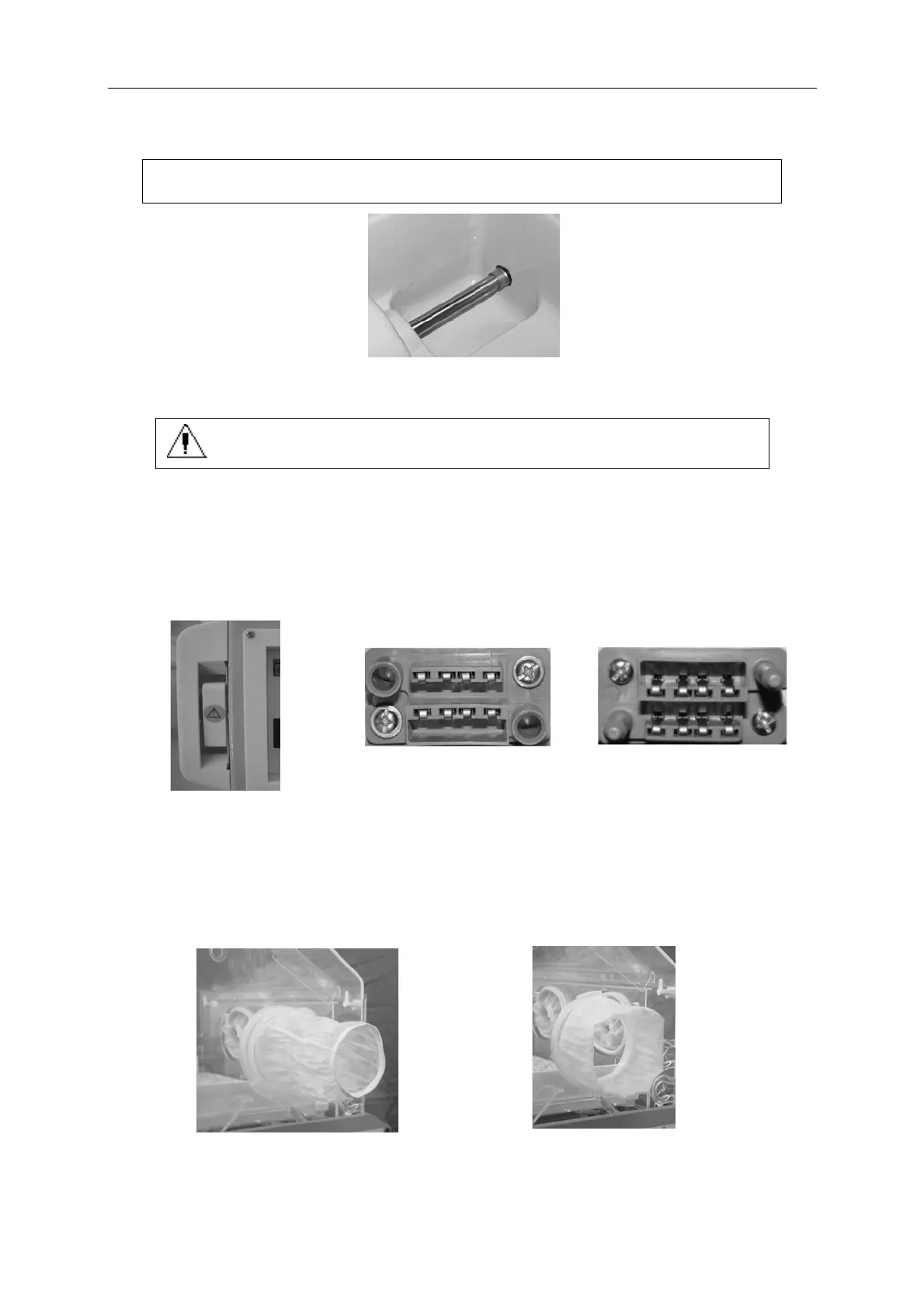
B. Install Air Intake Tube in the reverse steps as they are moved out. Installed Air Intake Tube
must comply to Figure 5.9.
NOTE: Air Intake Tube must be placed inside the Air Intake Tube Connector and
completely sealed.
FIGURE 5.9
C. Place Main Deck back.
WARNING: Be sure the two thumb screws that hold the Mattress
Tray are tightened.
D. Install the air curtain and the inner wall as figure 5.3 and 5.4 direct.
E. Install the controller as the figure 5.1 directs
Controller is the key unit of Incubator and must be installed carefully.
Insert Controller into Base Assembly. After the whole part is inserted into Base Assembly,
depress the snaps at both sides of Controller until they are parallel to the side then pull the
Controller outward. If the Controller is not loosened, it is already locked. (See Figure 5.10)
CAUTION:Power socket and plug of the humidity control are the power supply of the
incubator’s humidity control system. Do not force the controller in, or else the
power supply system will be dameged.
FIGURE 5.10
F. Rotating the iris entry sleeves, see figure 5.11.
Step 1: Install the elastic band over the inner ring of the port housing. Fold back and slip elastic
band over the outer ring of the port housing.
Power socket of humidity
control on the base
Power socket of humidity
control on the controller
Correctinstallation state


 To Next Page