© 2005-2016 Nira Control AB 23
In the wiring harness there’s a shielded wire marked “Crank” with to wires
and one shield. The same wire should be used for both hall sensors and
inductive sensors. Note the different sensor types are differently connected
in the NIRA i7x connector.
An accurate signal from the crank position sensor is crucial. Therefore, it is
very important to install the CKP sensor with diligence. A faulty installation or
a bad combination of CKP sensor and pulse wheel causes an unreliable
signal. In turn, an unreliable signal will make the engine run poorly.
It’s important that the sensor mounting bracket is solid and that the trig
wheel is 100 % aligned with the crankshaft.
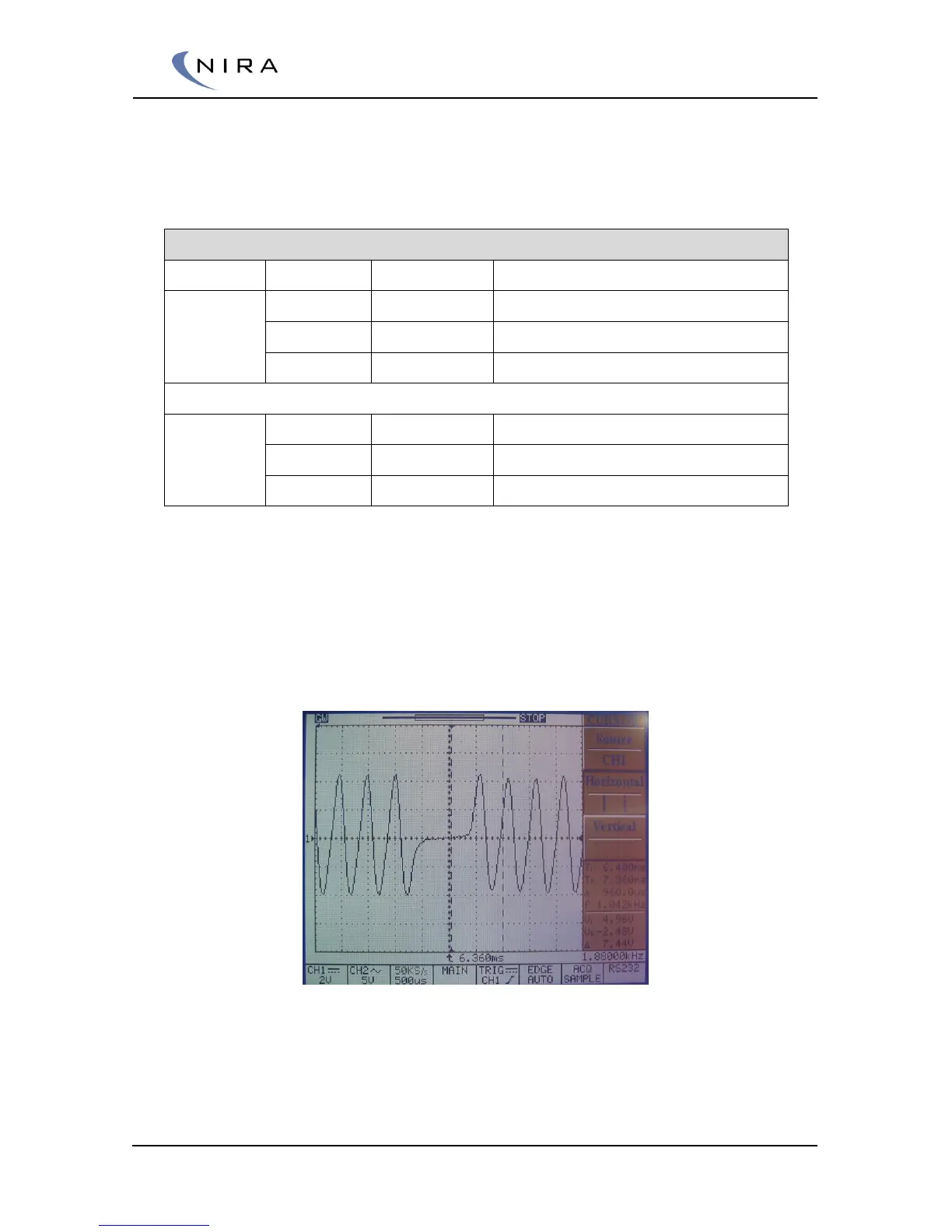
Example of an inductive CKP sensor signal when a ”2 lost” is detected from a pulse wheel
with a ”60 – 2 lost” pattern.
The signal from the CKP sensor should resemble the pattern in the image
above. It is recommended to use an oscilloscope to study the signal.
 Loading...