© 2005-2016 Nira Control AB 25
must be entered into NIRA rk and it is absolutely necessary to enter the
correct values to be able to start the engine.
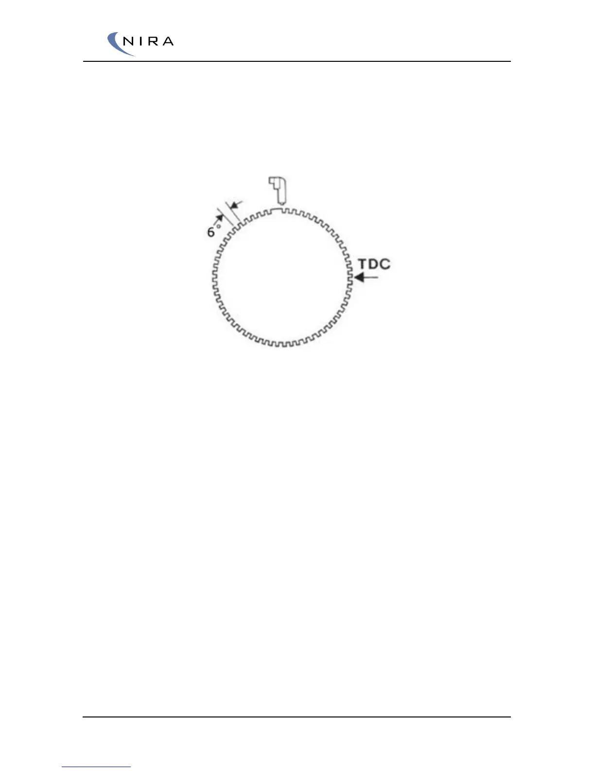
Some types of pulse wheels are made with holes drilled in a solid material.
These pulse wheels often have a reference point in the shape of a peak
instead of a valley – see the image below for sketch of a “60 – 1 lost” hole
with a peak as a reference point.
Pulse wheel with a ”60 – 1 lost” pattern and a peak instead of a valley as reference point.
Pulse wheels having a peak instead of a valley or a hole as a reference point
are more error prone since vibrations can cause false trigs when the reference
point passes the sensor. If you are fitting a new pulse wheel when installing
NIRA i7x, always choose a pulse wheel with a valley as reference point.
The trigger wheel mounts on the face of the crank pulley. If the crank pulley
is also a harmonic balancer, verify that it is in good condition and isn’t
slipping. Make sure the trig wheel is aligned on the pulley. If it is not
centered properly, the signal strength from the CKP sensor will vary and
ignition timing will drift back and forth.
The example below is given for fitting a “60 – 2 lost” pulse wheel: When
figuring out the angular placement of the trigger wheel, first turn the engine
to TDC for cylinder 1. Then place the trigger wheel such that the angle
between the “2-lost” window and the place where you plan on mounting the
CKP sensor is around 90-120 degrees. See picture 3-1 below. You will later
need to measure the exact angle, see section 3.1.2.
Once the trigger wheel has been fitted, mount the CKP sensor. The gap
between the CKP sensor and the trigger wheel should be 0.5-1.0mm. If the
gap is greater than 1.0 mm, the signal strength from the CKP sensor will vary
too much and timing will drift back and forth. Mount the sensor in a bracket
that allows for slight adjustments. Secure the CKP sensor wires with cable ties
to make sure they don’t interfere with e.g. engine drive belts.
 Loading...