B 2-10 Control
Unit Not Powering
On
@ontd.)
E
trffi
oLr
u
B
r
o
t23a5o
B
mt
JE
EI
ol7
e
rel
@F;;:l
x3
rJ
c
#
x2H
x1H
x3H
o
o
:
xs2H
o
:
xslH
1
2
3
o
Jl
'0"
o
o
o
F4
'0+
U
K1
3
4
41308644
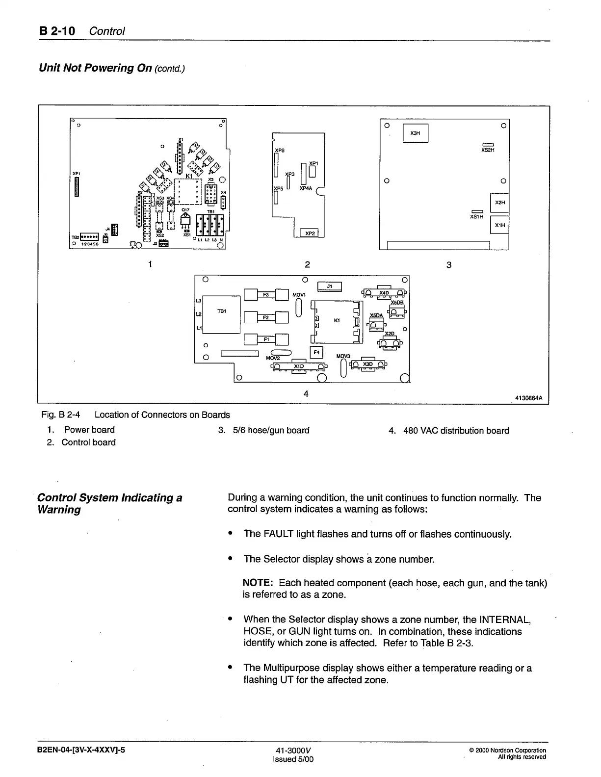
Fig. B 2-4 Location
of Connectors on Boards
1.
Power board
3. 5/6 hose/gun
board
2. Control board
Control System lndicating a
Warning
4. 480 VAC
distribution board
During
a warning
condition, the
unit
continues
to function normally. The
control system
indicates
a
warning
as follows:
a
The FAULT
light flashes
and turns off or flashes continuously.
The
Selector display
shows a zone number
NOTE:
Each
heated component
(each
hose,
each
gun,
and the tank)
is referred
to as a zone.
When
the Selector display
shows azone number,
the
INTERNAL,
HOSE, or
GUN
light
turns on. ln combination,
these indications
identify
which zone
is affected. Refer to Table B 2-3.
The Multipurpose
display shows
either a temperature reading or a
flashing
UT
for
the affected zone.
a
82EN-04-[3V-X-4XXU-s
4't-3000y
lssued
5/00
@
2000 Nordson
Corporatlon
All rights
reserued
 Loading...


