Control B 2-27
4.
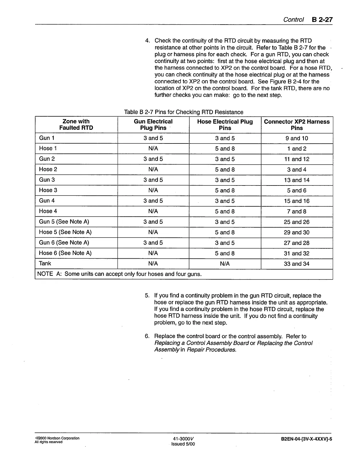
Check the continuity of
the RTD circuit by measuring the RTD
resistance at other
points
in the circuit. Refer
to
Table B 2-7 tor lhe
plug
or harness
pins
for each check. For a
gun
RTD,
you
can check
continuity at two
points:
first
at the hose electrical
plug
and then at
the harness
connected to XP2
on the control board. For a hose
RTD,
you
can check
continuity at the hose electrical
plug
or at the
harness
connected to XP2 on
the control board.
See
Figure B 2-4 for the
location of XP2
on the control board. For the
tank
RTD, there
are
no
further
checks
you
can make:
go
to the next step.
Table B 2-7 Pins for
Checking RTD Resistance
5.
lf
you
find
a continuity
problem
in the
gun
RTD circuit, replace the
hose or replace
the
gun
RTD harness
inside the unit as appropriate.
lf
you
find a continuity
problem
in
the hose RTD circuit, replace the
hose RTD harness
inside
the unit. lf
you
do not find a continuity
problem, go
to the next
step.
6.
Replace
the control
board or the control
assembly. Refer to
Replacing
a Control Assembly Board
or Replacing the
Control
Assembly
in Repai r
Procedures.
Zone with
Faulted RTD
Gun Electrical
PIug
Pins
'
Hose Electrical PIug
Pins
Connector
XP2 Harness
Pins
Gun
1
3and5
3and5
9 and 10
Hose 1
N/A
5and8 1and2
Gun
2
3and5
3and5
11
and
1 2
Hose 2
NiA
5andB
3and4
Gun 3
3and5
3and5 13 and 14
Hose 3
N/A
5and8
5and6
Gun 4
3and5
3and5 15 and 16
Hose 4
N/A
5andB 7and8
Gun 5
(See
Note A)
3and5
3and5 25 and26
Hose
5
(See
Note A)
N/A
5andB 29 and 30
Gun 6
(See
Note A)
3and5 3and5
27 and28
Hose
6
(See
Note A) N/A
5and8
31 and 32
Tank
N/A
N/A 33 and 34
NOTE A:
Some
units
can accept only four hoses and four
guns.
@000 Nordson
Corporalion
All rights reserued
41-3000y
lssued
5/00
82 EN-04-[3V-X-4XXVj-s
 Loading...


