E 1-2 Series 3000V
lnput/Output
Board
1. lntroduction
@ontd.)
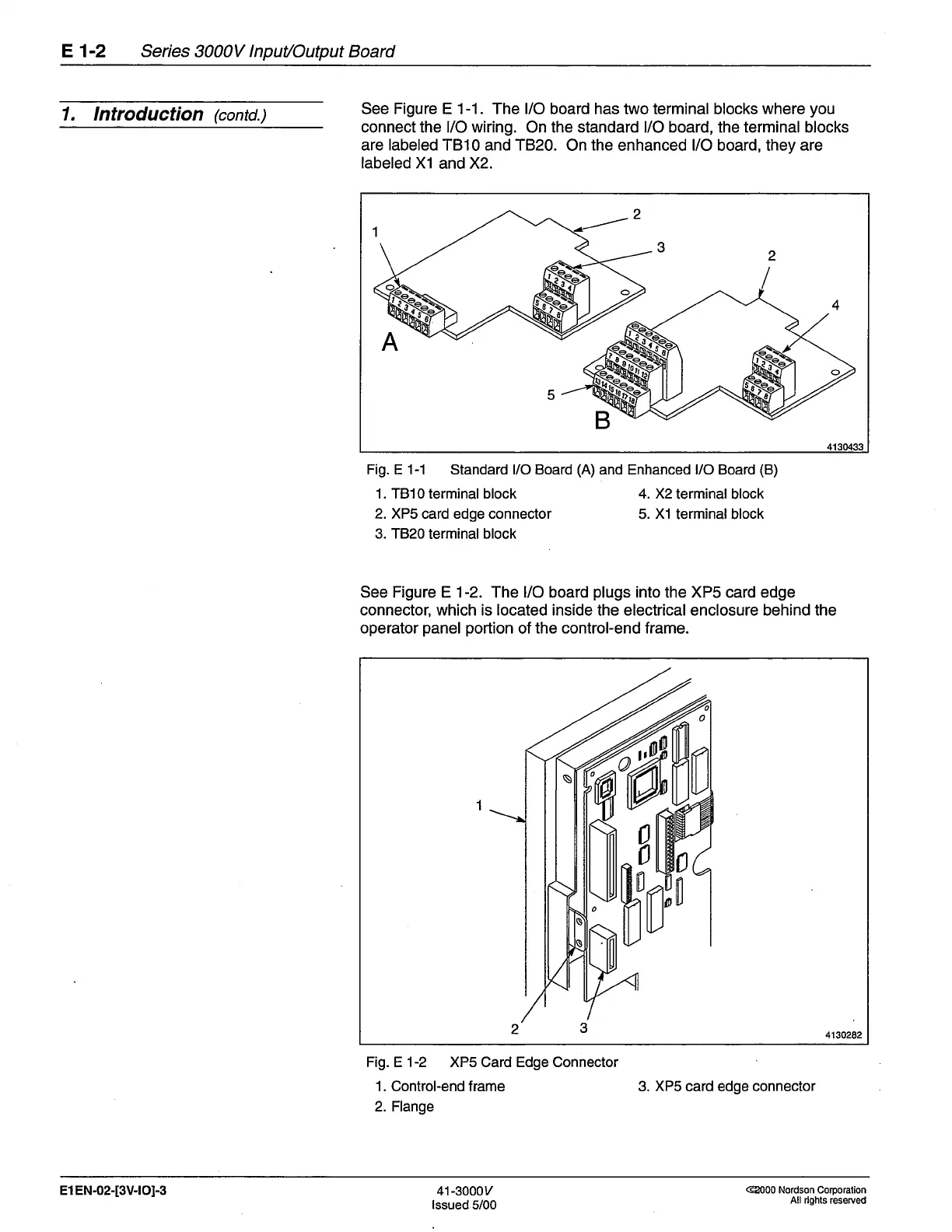
See Figure E 1-1. The l/O board has two terminal
blocks
where
you
connect the l/O wiring.
On
the standard l/O board,
the
terminal blocks
are labeled TB10 and T820.
On
the
enhanced l/O board, they are
labeled X1
and X2.
Fig.
E 1-1 Standard l/O Board
(A)
and Enhanced l/O Board
(B)
1. TB10 terminal block 4. X2
terminal block
2. XP5 card edge connector
5.
X1
terminal block
3. TB20
terminal block
See Figure E 1-2. The l/O board
plugs
into the XPS
card
edge
connector, which is located inside the electrical enclosure behind the
operator
panel portion
of
the control-end frame.
Fig. E 1-2 XP5 Card Edge Connector
1.
Control-end frame
2. Flange
3. XPs card edge connector
2
1
3
2
4
41304:t3
A
5
B
l,
0
0
fl
1
0
fl
o
3
2
4150282
El EN-02-[3V-rOI-3
41-3000v
lssued
5/00
@000 Nordson CoIporation
All rights reseryed
 Loading...


