CRC200R USER GUIDE ISSUE 02
3-2
3.2 Power Supply and Cabling Requirements
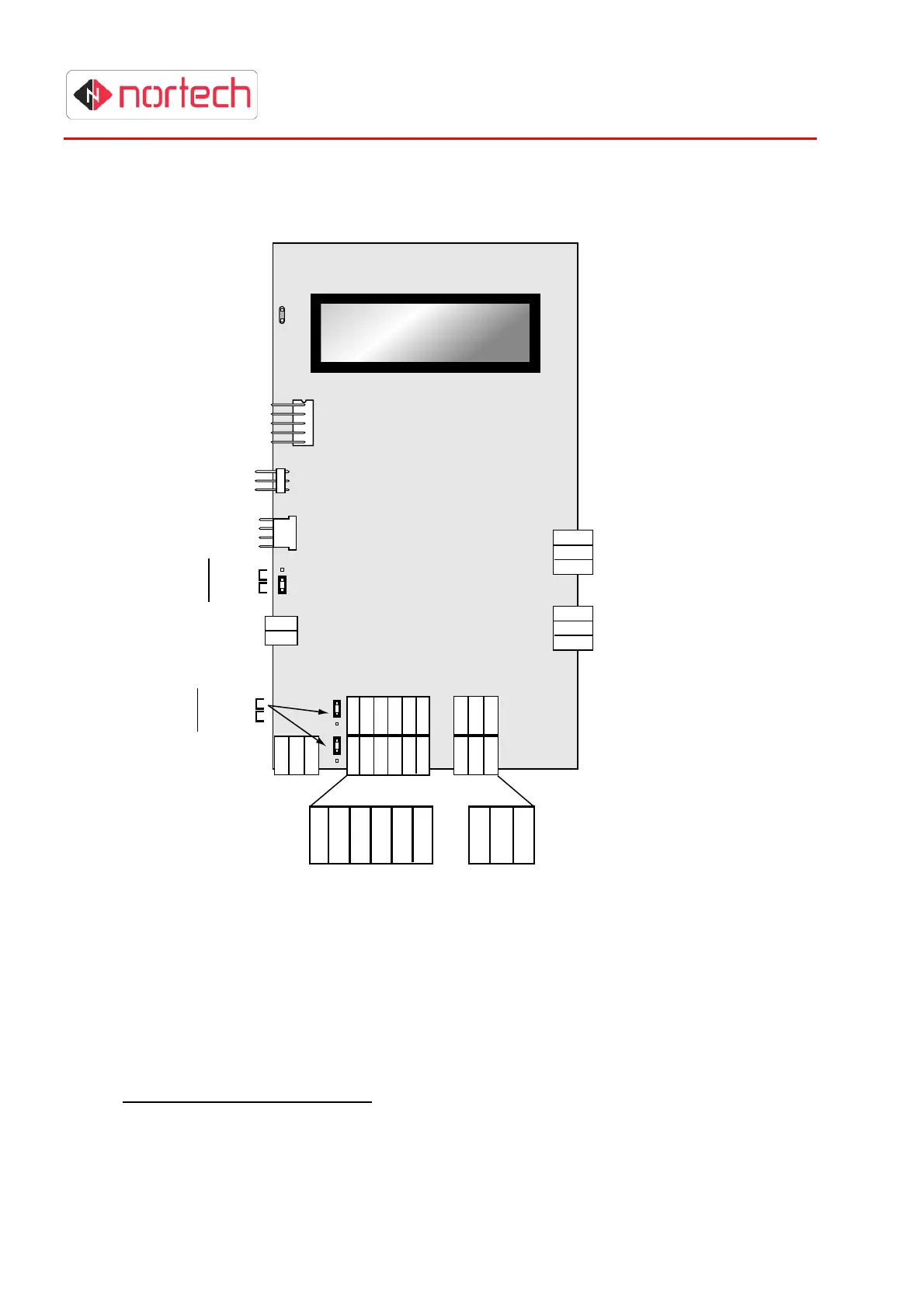
The diagram below shows the CRC200R with the cover removed. All terminal blocks and
configuration jumpers are shown.
Figure 3.1 – CRC200R Connection Diagram
3.2.1 Power Supply
The CRC200R must be fed from a suitable power supply that is capable of supplying a voltage
between 12 and 24 volts DC (see warning below). The supply current requirements for the unit
are100 milliamps quiescent, and 230 milliamps while reading with a passive reader. Some reader
types such as motorised readers need to be powered by a separate supply (refer to the reader’s
installation instructions).
Connect the power supply to the power input connector at the bottom left of the unit (see diagram
above) Do not apply power at this stage.
N/O
N/C
Comm
N/O
N/C
Comm
Relay 1
Relay 2
RS232
RS232
RS485
Comm ’s
Select
Reader
oltage
Select
Reader 1
Reader 2
5V
As supply
12 - 24 VDC
D+
D-
GND
RS485
+ve
-ve
Clk/D1
Dat/D0
LED
Capt
0v
REX
Mon
NOT
USED
NOT
USED
NOT
USED
+
-