CRC200R USER GUIDE ISSUE 02
3-1
3 INSTALLATION
3.1 Mounting the Unit
The CRC200 can be wall-mounted when used indoors or
fixed inside a weatherproof housing for outdoor use.
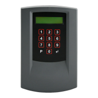
Identify a location convenient for cabling while ensuring
that the LCD screen and keypad are easily accessible for
programming the unit and carrying out diagnostics. Also
ensure that the CRC200 is protected from excessive
temperatures and moisture.
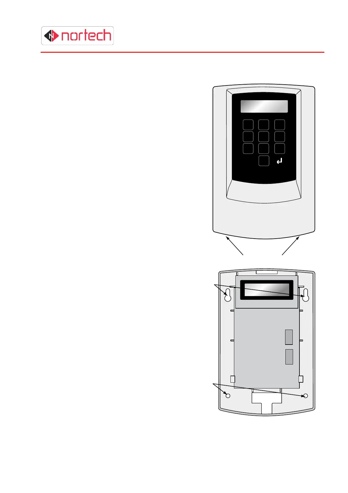
The mounting procedure is as follows:
1. Release the front cover from the main unit by
pressing the securing buttons at the base of the
unit while you lift off the cover from the bottom
(hinging the cover at the top).
2. Carefully unplug the ribbon cable linking the
cover to the main unit. Avoid pulling or bending
the ribbon cable.
3. Completely remove the front cover.
4. Mount the unit on the mounting surface through
the 2 keyhole slots and 2 mounting holes in the
back plate. Use 4 appropriate screws or nuts/bolt
(M4) according to the type of mounting
surface.
5. After wiring the unit, support the cover
with one hand and carefully re-insert the
end of the ribbon cable into its socket.
Refit the cover by engaging the top of
the cover with the top of the housing
and hinging in the bottom of the cover
until the securing buttons are fully
engaged in the housing.
Note: If the unit is already mounted in a
plastic enclosure with PSU, mount the
enclosure as follows:
There are 3 mounting holes in the back
panel of the enclosure with an optional
fourth hole at the bottom of the back
panel. Choose a location where there is
sufficient space to run cables into one
or more of the cable apertures
(knockouts provided in top and bottom).
Mount the unit on the planned mounting
surface use 4 appropriate screws or
nuts/bolt (M4) according to the type of
mounting surface.
Keyhole
Slots
Mounting
Holes
1 2 3
4 5 6
7 8 9
P 0
Retaining Buttons