24
External Audio Input Routing
Displayed as: AudioInput
Initial value: Off
Range of adjustment: Off, PreFilt, PostFilt
Stereo audio from external equipment connected to Summit’s external inputs
10
can
be inserted into the signal processing paths of each synth either before (PreFilt) or after
(PostFilt) the filter section. When a Multi Patch is selected, you can independently select
how the external signal is routed to either Part A or Part B, or both. Note that an external
audio signal will not be heard if the VCA is not being triggered. If no notes are being
played, the VCA is not being opened by the keyboard and no audio can pass through.
When using Summit to process external audio in the same way as you
would use an FX processor, you can turn down the mixer inputs
(Oscillators, Noise and Ring Modulator) so that their sounds are not
combined with the external input signal. If you then hold a note on and
press Key Latch, the VCA will remain open at all times, allowing the external signal to be
constantly processed.
When using Summit to process external audio, it is important to remember
that the number of voices held open can affect the external audio’s input
level. The more voices held open, the more “instances” there are of the
external signal being passed through the synth’s processing.
However, if too many voices are used it can cause unwanted level clipping. You should
experiment, but for the best results, one or two notes will often provide enough of a
desired signal for processing.
Note that the external audio inputs may also be routed to the FX section. This routing is
completely independent of the that enabled by AudioInput, and is enabled in the
Settings menu. See page 42.
Voice Menu Page 4:
VOICE 4/4
FltShpMore LP > HP H
FltFreqSep +0
Dual Filter Options
Displayed as: FltShpMore
Initial value: LP > HP
Range of adjustment: LP > HP, LP > BP, HP > BP, LP + HP, LP + BP,
HP + BP, LP + LP, BP + BP, HP + HP
As explained in the Filter Section description (see page 27), Summit offers two separate
filters, each of which may be configured as low-pass, band-pass or high-pass by the Filter
section’s Shape control
58
. For the three settings LP, BP and HP, the Slope control
59
inserts either a single filter (12dB) or two identical filters in series (24dB) into the
signal path. When Slope is set to Dual, the Voice menu page above is displayed and
Slope is fixed at 12dB.
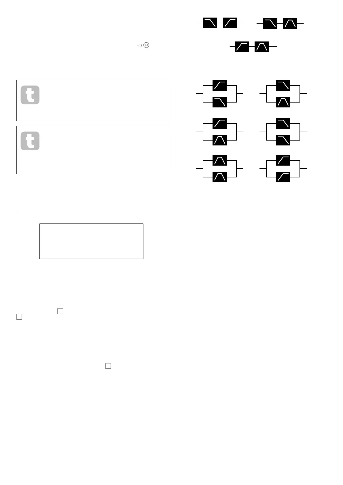
The FltShpMore parameter offers nine further combinations of the two filters. The first
three, those including a ‘>’ symbol, place two dissimilar filters in series, while the other six,
those including a ‘+’ symbol, place two filters in parallel. Note that in the case of parallel
configurations, the two filters may be of the same type. These dual filter options give the
filter sections greatly increased flexibility over conventional designs employing a single,
configurable filter. While the main Frequency control
60
continues to adjust the cut-off
(or centre) frequency of both filters, the second parameter on this page, FltFreqSep,
allows the two cut-off (or centre) frequencies to be different, or “separated”.
Series and parallel combinations of two filters result in radically different overall frequency
responses. With filters in series, the combined effect is
subtractive
: that is, the harmonic
content of the signal after the first filter will already have been reduced by its action, and
will then be further reduced by the second. Therefore frequencies will be removed by both
filters. Conversely, the combined effect of parallel filters may be considered as
additive
,
because the same signal is applied to
both
filters, so frequencies removed by one filter may
be passed by the other, depending on their relative type and cut-off (or centre) frequencies.
In general, combining filters in parallel is likely to produce a response shape with a peak or
dip between the frequencies of the two filters, but a wide range of shapes can be created
by combining two filters of different types. The value of the “separation” parameter,
FltFreqSep (see below), also has a major effect on the resulting frequency response.
(a) LP > HP
(b) LP > BP
(c) HP > BP
(d) LP + HP
(e) LP + BP
(f) HP + BP
(g) LP + LP
(h) BP + BP (i) HP + HP
FILTERS IN SERIES
FILTERS IN PARALLEL
Filter frequency separation
Displayed as: FltFreqSep
Initial value: 0
Range of adjustment: -64 to +63
Two filters configured in either series or parallel by selecting one of the dual filter
options may have different frequencies. The difference – or separation – of the two filter
frequencies is set by the FltFreqSep parameter. When separation is zero, the two
filters have the same frequency. Positive values of FltFreqSep will lower the frequency
of the first filter while increasing that of the second, thus “separating” the response curves
of the two filter sections. The converse applies with negative values: the frequency of the
first filter increase while that of the second decreases, so that the frequencies effectively
“cross over”.
The audible effect of these options will largely depend on the two filter types selected by
FltShpMore. The “first” and “second” filters referred to in the previous paragraph are
the two listed in the FltShpMore setting, e.g., with FltShpMore set to HP + BP, the
“first” filter will be a high-pass type and the second a band-pass type.
In all dual filter options, the resultant frequency response from the combination will have
two turning points if FltFreqSep is set to something other zero, thereby giving the
two filters different frequencies. Frequency always adjusts the overall filter combination
regardless of the separation, but will maintain the “offset” between the two cut-off (or
centre) frequencies – as a constant octave value - as it is varied.